
Touch panel

a technology of touch panel and touch screen, which is applied in the field of touch panel, can solve the problems of affecting the appearance of the product, and achieve the effects of avoiding deterioration, avoiding color change of the first mask structure in the mask area, and reducing the size of the mask area

Active Publication Date: 2018-06-19
TPK TOUCH SOLUTIONS (XIAMEN) INC
View PDF7 Cites 0 Cited by
  • Summary
  • Abstract
  • Description
  • Claims
  • Application Information

AI Technical Summary

Benefits of technology

[0005]In view of the foregoing subject, this disclosure provides a touch panel whereby the mask structure in the mask area can be prevented from being changed in color.
[0025]As mentioned above, in the touch panel of this disclosure, the dense structure masks the first mask structure and has a higher dense degree and a capability to resist high temperature. Therefore, the first mask structure, is protected, so that the deterioration and the color change of the first mask structure in the mask area can be avoided. Thereby, the appearance of the touch panel looks better.

Problems solved by technology

However, when the mask structure is formed by the material of other colors, especially the material of light color (such as white ink), in the border area, the mask structure will be easily changed in color due to the influence of the temperature, oxygen or chemical liquids in the subsequent process since the mask structure is more sensitive to the temperature (for example, the white ink will be yellowed), and, the appearance of the product will be affected.

Method used


Image

  • Touch panel
  • Touch panel
  • Touch panel

Examples


Embodiment Construction

[0037]The present disclosure will be apparent from the following detailed description, which proceeds with reference to the accompanying drawings, wherein the same references relate to the same elements.

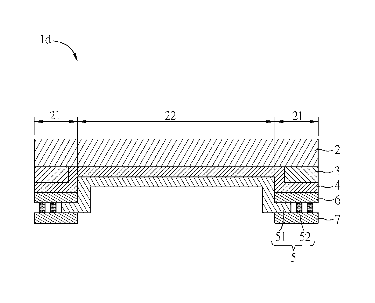
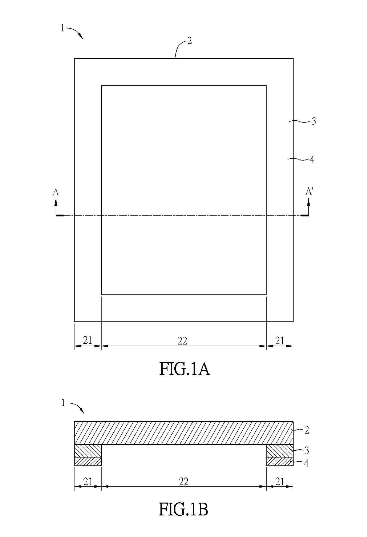
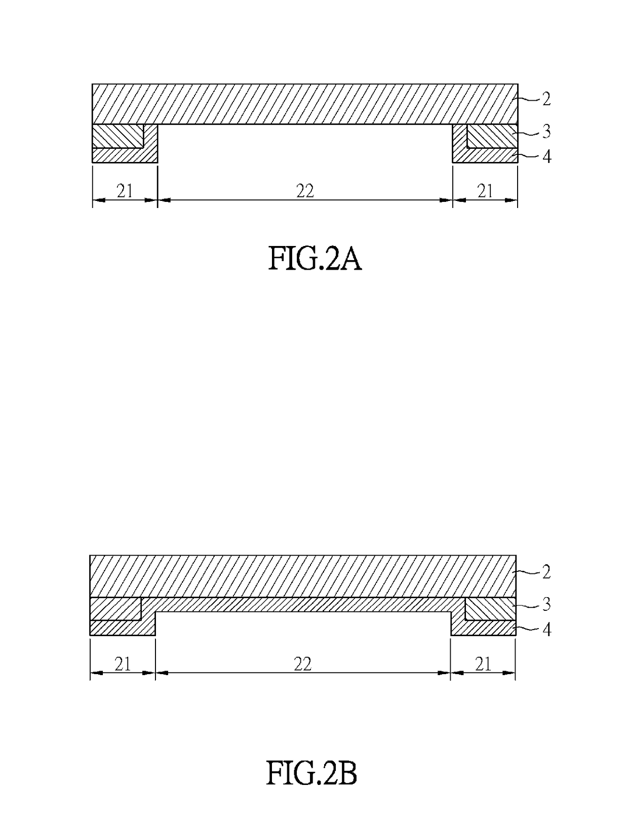
[0038]FIG. 1A is a schematic top-view diagram of a touch panel 1 of some embodiments of the disclosure, and FIG. 1B is a schematic sectional diagram of FIG. 1A taken along the line A-A′. As shown in FIGS. 1A and 1B, the touch panel 1 includes a substrate 2, a first mask structure 3 and a dense structure 4. The first mask structure 3 is disposed on a surface of the substrate 2 to divide the substrate 2 into a mask area 21 and a visible area 22 disposed adjacent to the mask area 21. The mask area 21 is disposed corresponding to the first mask structure 3. In some embodiments, the mask area 21 is disposed around the visible area 22. In other embodiments, the mask area 21 may be disposed on at least one side of the visible area 22. The dense structure 4 is disposed on the first mask stru...


PUM


Abstract

A touch panel comprises a substrate, a first mask structure and a dense structure. The first mask structure is disposed on a surface of the substrate and divides the substrate into a mask area and a visible area disposed adjacent to the mask area. The first mask structure is disposed in the mask area. The dense structure at least masks a surface of the first mask structure farther from the substrate.

Description

[0001]This Non-provisional application claims priority under 35 U.S.C. § 119(a) on Patent Application No(s). 201410718261.7 filed in People's Republic of China on Dec. 1, 2014, the entire contents of which are hereby incorporated by reference.BACKGROUND OF THE INVENTIONTechnical Field[0002]This disclosure relates to a touch panel.Related Art[0003]In current touch technology, a circuit is generally disposed at a periphery of a sensing area of a touch panel and touch signals can be transmitted to a related processing circuit through the circuit for processing. Furthermore, for aesthetic reasons, a mask structure, such as ink or photoresist material, is generally disposed at a portion of the touch panel opposite to the circuit for masking the circuit, so that the area having the mask structure (mask area), the so-called border area, is formed.[0004]In general, the border area is mainly black, masking the circuit by the low transmittance property of the black ink or the photoresist mate...

Claims


Application Information

Patent Timeline
Patent Type & Authority Patents(United States)
IPC IPC(8): G06F3/041G06F3/044
CPCG06F3/041G06F3/044G06F3/04164
Inventor JIANG, YAU-CHENLAI, BINWU, DEFAYAN, JIANBINXU, LIANGZHENZHANG, YU
Owner TPK TOUCH SOLUTIONS (XIAMEN) INC
Learn More