Electrostatic focusing femtosecond stripe image converter tube

A technology of electrostatic focusing and phase-changing tubes, which is applied in the direction of discharge tubes, image conversion/image amplification tubes, cathode ray tubes/electron beam tubes, etc., can solve the problems of image plane instability and low time resolution, and achieve image plane stability , high temporal resolution, and high spatial resolution

Inactive Publication Date: 2007-07-04
XI'AN INST OF OPTICS & FINE MECHANICS - CHINESE ACAD OF SCI
View PDF0 Cites 15 Cited by
  • Summary
  • Abstract
  • Description
  • Claims
  • Application Information

AI Technical Summary

Problems solved by technology

[0003] The purpose of the present invention is to provide a high time resolution, high spatial resolution electrostatic focusing femtosecond stripe phase-changing tube, which on the one hand solves the technical problem of unstable image plane of the existing domestic short magnetic focusing stripe phase-changing tube, on the other hand Solve the technical problem of low time resolution of the traditional electrostatic focusing stripe phase change tube

Method used


Image

  • Electrostatic focusing femtosecond stripe image converter tube
  • Electrostatic focusing femtosecond stripe image converter tube
  • Electrostatic focusing femtosecond stripe image converter tube

Examples


Embodiment Construction

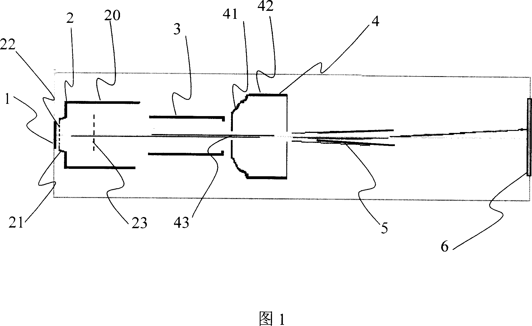
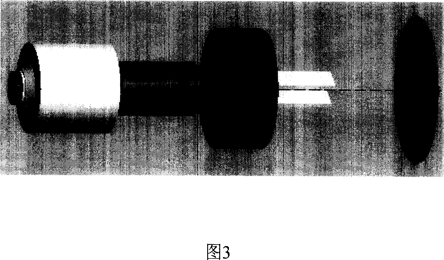
[0022] Referring to Figure 1 and Figure 3, the structure of an electrostatic focusing femtosecond stripe phase-changing tube of the present invention includes a cathode 1, a grid 2, a focusing electrode 3, an anode 4, a deflection plate 5 and a fluorescent screen 6, the cathode 1 is in the shape of a disc, and the grid Pole main body 20 is cylindrical, and its end near cathode 1 is provided with an outer boss 21, and first grid 22 is arranged on outer boss 21, and this first grid 22 is on the one hand between cathode 1 and grid. 2 forms a strong electric field to ensure that the electrons have a small time dispersion between the cathode 1 and the grid 2. On the other hand, the accelerated photoelectrons can pass through the small holes of the grid. A second grid 23 may be provided inside the second half of the grid 2 , the voltage of which is 100-200V lower than that of the grid 2 , so as to intercept the secondary electrons generated on the first grid 22 . The focusing electr...


PUM


Abstract

The invention designs electrostatic focused femtosecond stripes disguise tube, the disguised tube cathode 1 being a circular plate-shaped; the main-body of grid 2 being the cylindrical shape, the end having a outer convex station 21, the convex station 21 having a grid network; the focused electrode 3 using cylindrical structure; the end of the anode 4 near the focused electrode 3 being bowl structure, the small end surface of the bowl structure having a center hole 43, and the end near the deflector plate 5 being cylinder shape structure; the deflector plate 5 being a pair of tilted strip plate; the diameter of the main-body of grid 2 compared with the diameter of the focused electrode 3 being ratio of 1.1~2.8. Through the said structure, and using Monte Carlo method for sampling, using the finite difference method to calculate the electron distribution, using four bands Runge-Kutta method to simulate and trace a large number of photoelectrons trace for statistic and analysis, and finally it provides the basic parameters of the disguised tube space modulation transfer function and time distinguish ability.

Description

technical field [0001] The invention relates to a femtosecond stripe phase transformation tube, in particular to an electrostatic focusing femtosecond stripe phase transformation tube. Background technique [0002] The theoretical limit of the time resolution capability of the striped phase transition tube is 10fs, and people have been striving towards this direction for many years. Significant progress has been made in improving time resolution abroad: Hamamatsu Corporation of Japan and the Institute of General Physics of the Russian Academy of Sciences have developed a phase-changing tube with a time resolution of 200 fs. Chang Zenghu's research group at the University of Kansas in the United States increased the time resolution of the electrostatically focused phase-changing tube to 280 fs (integral mode) by placing a 5 μm wide slit between the anode and the deflector plate, and carried out a time-resolving 100 fs phase-changing tube. tube research work. In addition to ...

Claims


Application Information

Patent Timeline
Patent Type & Authority Applications(China)
IPC IPC(8): H01J31/50H01J29/02
Inventor 田进寿白永林刘百玉欧阳娴白晓红杨文正王琛黄蕾
Owner XI'AN INST OF OPTICS & FINE MECHANICS - CHINESE ACAD OF SCI
Why Eureka
Try Eureka