Magnetron

A magnetron and magnet technology, applied in the field of magnetron, can solve problems such as adverse effects of peripheral equipment and human injury

Inactive Publication Date: 2007-07-04
LG ELECTRONICS INC
View PDF0 Cites 5 Cited by
  • Summary
  • Abstract
  • Description
  • Claims
  • Application Information

AI Technical Summary

Problems solved by technology

The third harmonic frequency and the fifth harmonic frequency leak out of the magnetron, which may cause harm to the human body, and may also adversely affect peripheral equipment such as TV receivers or radios

Method used


Image

  • Magnetron
  • Magnetron
  • Magnetron

Examples


Embodiment Construction

[0030] The content shown here is exemplary, and is only used to illustrate and discuss the embodiments of the present invention, and to provide what is considered the most valuable and easy-to-understand description of the principles and concepts of the present invention. Therefore, no structural details of the invention are shown herein in a more detailed manner but only information necessary for a basic understanding of the invention is provided. In view of the disclosure and the accompanying drawings, those skilled in the art will readily understand how to practice the several forms of the invention.

[0031] Reference will now be made in detail to the preferred embodiments of the invention, examples of which are illustrated in the accompanying drawings.

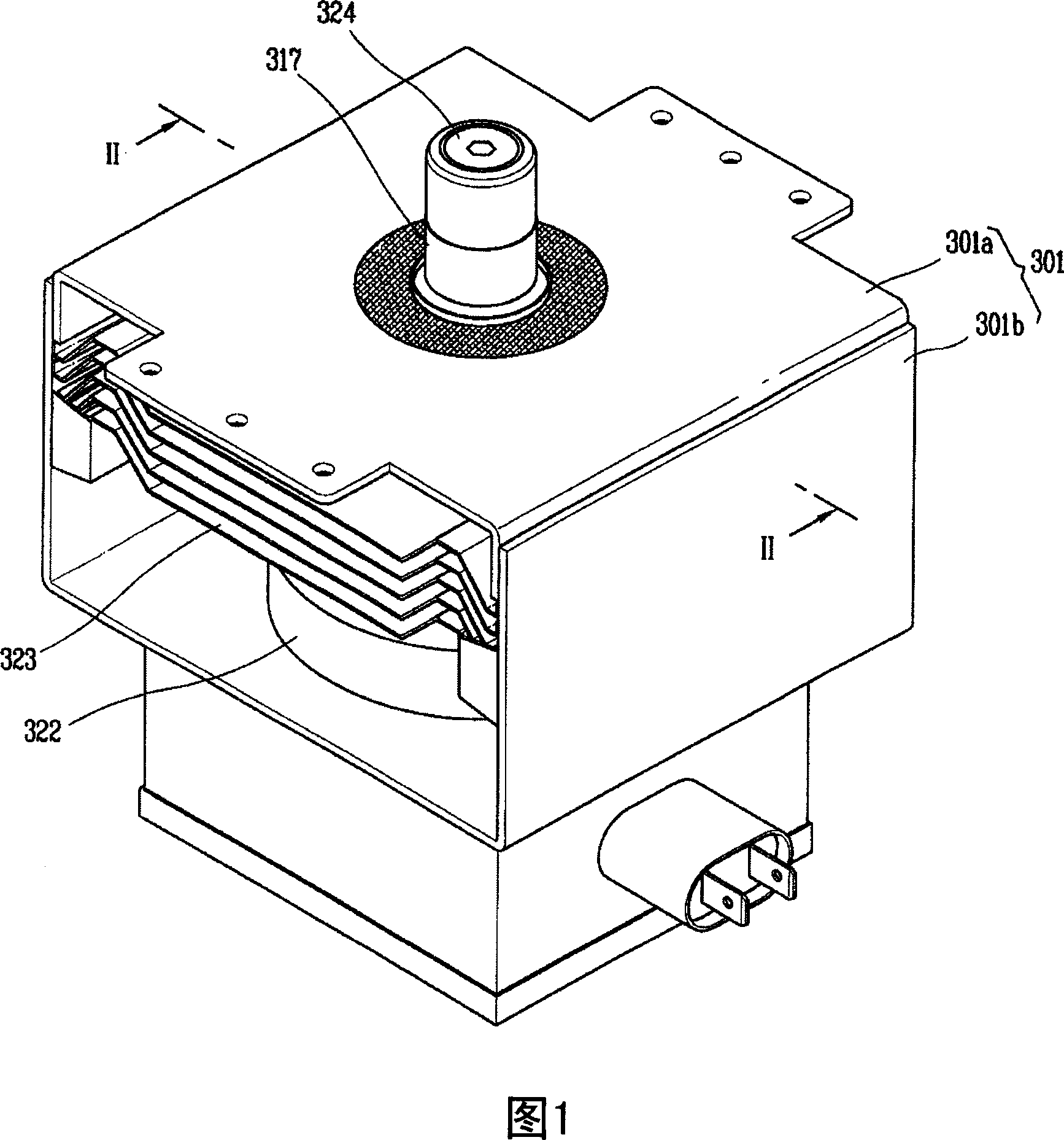
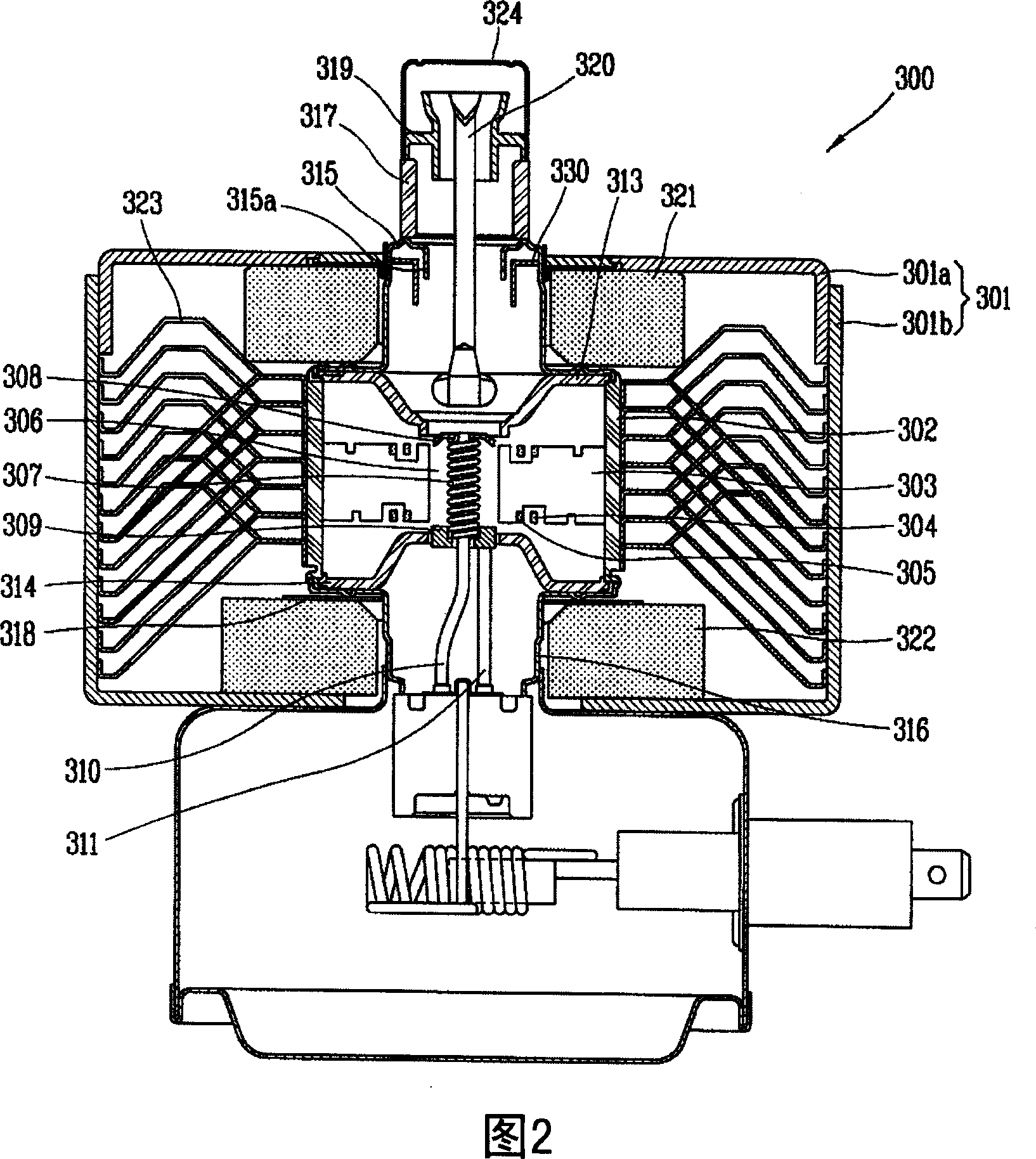
[0032] The magnetron according to the present invention includes a yoke, the inner space of which is formed, for example, by combining an upper (or first) yoke and a lower (or second) yoke; the upper (or first) magnet and...


PUM


Abstract

A magnetron is provided including a yoke having an inner space; a first magnet provided at one end of the inner space, a second magnet provided at a second end of the inner space, the second magnet being axially spaced from the first magnet. Further, there is an anode cylinder that generates a high frequency provided between the first magnet and the second magnet; a first pole piece and a second pole piece provided proximate first and second openings of the anode cylinder, respectively. Additionally, a seal that prevents outward leakage and has an inward protrusion extending axially toward the anode cylinder; and a choke filter, provided beneath a free end of the inwardly bent end of the seal to prevent outward leakage, may be provided.

Description

technical field [0001] The invention relates to a magnetron, in particular to a magnetron that can prevent the third harmonic and the fifth harmonic generated by it from leaking outward, and can prevent the high frequency band and low frequency band of the third harmonic and the fifth harmonic Magnetron. Background technique [0002] FIG. 1 is a perspective view showing a magnetron according to the conventional art. FIG. 2 is a sectional view taken along line 'II-II' in FIG. 1 . FIG. 3 is a perspective view showing the choke filter in FIG. 1, and FIGS. 4A and 4B are diagrams showing noise on third harmonic bands and fifth harmonic bands in a microwave oven to which a conventional magnetron is applied. [0003] As shown in the figure, the conventional magnetron includes a yoke 301, and the inner space of the yoke 301 is formed by combining an upper yoke 301a and a lower yoke 301b; an upper magnet 321 and a lower magnet 322 are accommodated in the inner space, and respectiv...

Claims


Application Information

Patent Timeline
Patent Type & Authority Applications(China)
IPC IPC(8): H01J23/54H01J25/50
CPCH01J25/50H01J23/54H01J23/15H01J25/587
Inventor 白承元李钟寿
Owner LG ELECTRONICS INC
Why Eureka
Try Eureka