
Fan system and its braking method

A fan system and braking technology, applied in the control system, the deceleration device of the DC motor, the deceleration device of the AC motor, etc., can solve the problems of high capacitor cost, failure of braking function, cost impact, etc.

Active Publication Date: 2007-06-27
DELTA ELECTRONICS INC
View PDF0 Cites 10 Cited by
  • Summary
  • Abstract
  • Description
  • Claims
  • Application Information

AI Technical Summary

Problems solved by technology

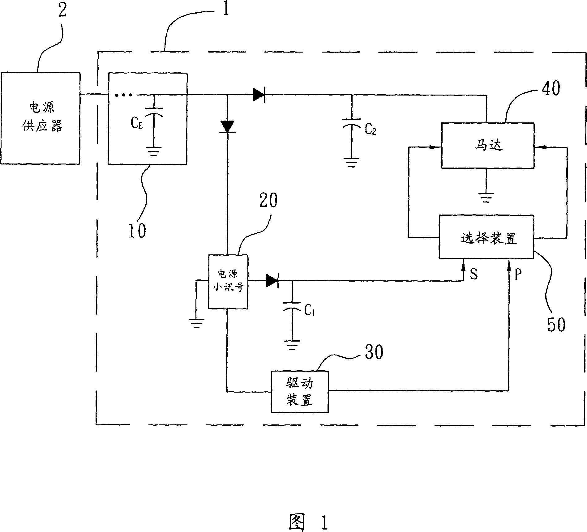
[0005] But in fact, in the energy storage capacitor C E When discharging, the driving device 30 also receives the power and generates the driving signal P to the motor 40, and because the first capacitor C 1 Like the drive device 30, it belongs to the control path, so the input time and potential of the start signal S and the drive signal P are very close, so the selection device 50 may choose to receive the drive signal P instead of the start signal S , thus causing the brake function to fail
[0006] In addition, because there are two branch paths on the control path (the first capacitor C 1 with the drive unit 30), so the energy storage capacitor C E It must be a large-capacity capacitor, so as to provide sufficient power for the power supply path and the control path, but the cost of large-capacity capacitors is high, and it will inevitably affect the cost during mass production, so there is also a need for improvement

Method used


Image

  • Fan system and its braking method
  • Fan system and its braking method
  • Fan system and its braking method

Examples


Embodiment Construction

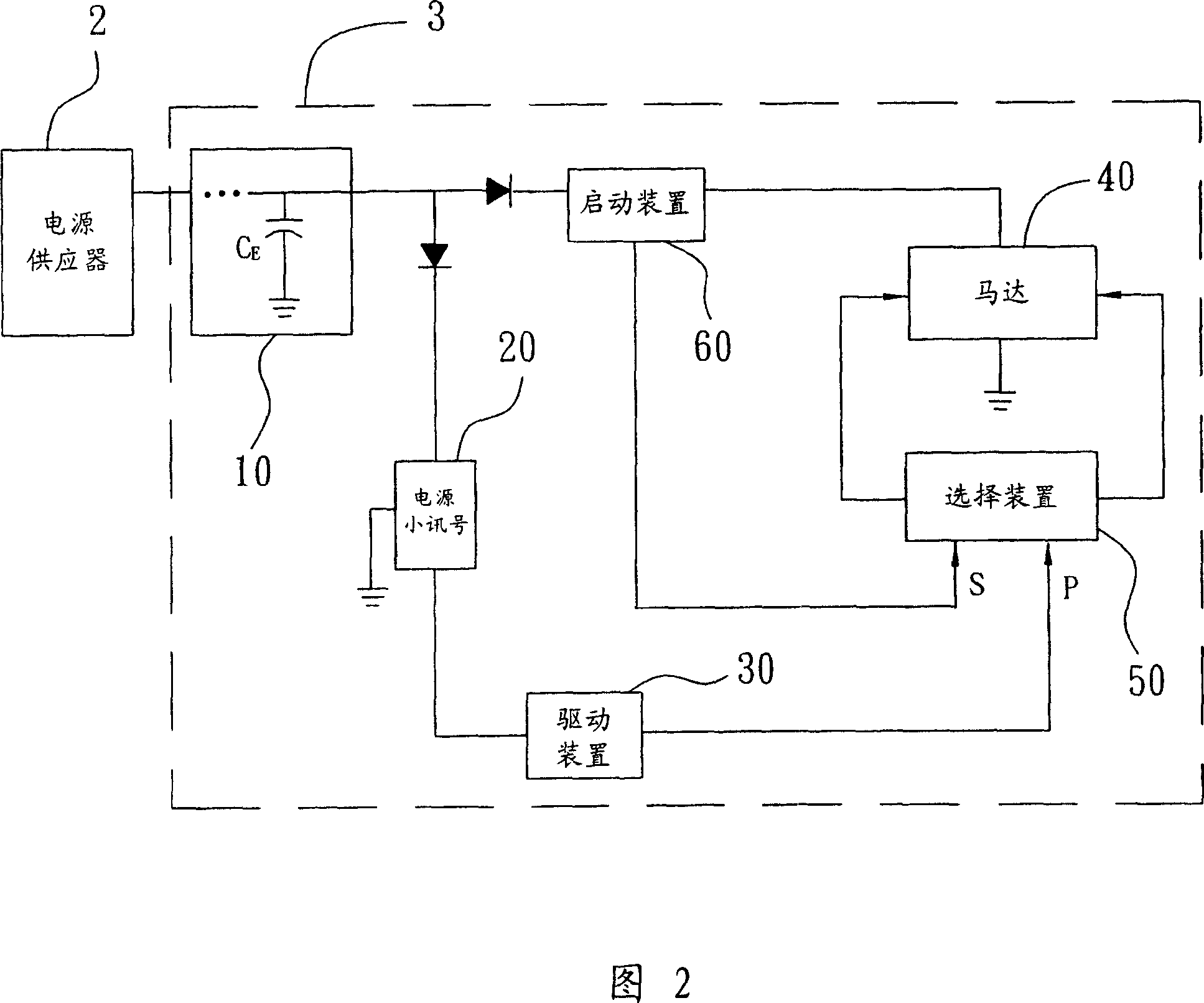
[0027] Referring to FIG. 2 , FIG. 2 is a schematic diagram of the composition of the fan system of the present invention. Wherein the fan system 3 is electrically connected to a power supply 2, and receives a power generated by the power supply 2, and the fan system 3 is composed of an energy storage device 10, a small signal power supply 20, a driving device 30, A motor 40, a selection device 50 and a starting device 60 are formed, wherein the energy storage device 10 is electrically connected to the power supply 2, and it receives and stores the power (as shown in the figure, an energy storage Capacitor C E stored electrical energy), the motor 40 is electrically connected to the energy storage device 10 and receives the power supply, the drive device 30 is electrically connected between the energy storage device 10 and the motor 40 to form a control path, and the drive device 30 is based on The power supply generates a drive signal P to the motor 40, the starting device 60 ...


PUM


Abstract

This invention provides a fan system connected to a supply provider and receiving a supply generated by the provider composed of an energy storage device, a motor, a drive device and a start up device, in which, the energy storage device receives and stores said supply, said motor is connected with said energy storage device and receives said supply, said drive device is connected between the energy storage device and the motor to form a control path, said start up device is connected between the energy storage device and said motor to form a supply path. When said fan system does not receive the supply of said provider, said storage device will release the stored supply, and said start up device generates an initiating signal to said motor to form a short loop to brake.

Description

technical field [0001] The invention relates to a fan system, in particular to a fan system with a braking function. Background technique [0002] Due to the continuous increase in the amount of information processing in electronic systems and the rapid, continuous and uninterrupted user requirements, more and more attention has been paid to the heat dissipation requirements in electronic systems. At present, fan systems are mostly used to provide heat dissipation effects, even as fans The system no longer receives power because the power of the electronic system is turned off, or it is separated from the electronic system itself. The motor in the fan system will still run for a period of time according to its inertia. If the user accidentally touches it at this time, it is extremely dangerous. It may cause injury; moreover, the inertial effect will also increase the waiting time for turning on the power again or connecting back to the electronic system, which is really a pr...

Claims


Application Information

Patent Timeline
Patent Type & Authority Applications(China)
IPC IPC(8): H02P3/00H02P3/12H02P3/22
Inventor 魏佳宾陈忆伦曾伟硕黄文喜
Owner DELTA ELECTRONICS INC
Learn More