Eureka AIR delivers breakthrough ideas for toughest innovation challenges, trusted by R&D personnel around the world.

Pneumatic tire

A technology for pneumatic tires and treads, applied to the reinforcement layer of pneumatic tires, tire parts, wheels, etc., can solve the problems of quietness and poor ride comfort, and achieve reinforcement unevenness, small road noise, and good ride comfort sexual effect

Active Publication Date: 2007-06-27
SUMITOMO RUBBER IND LTD
View PDF2 Cites 5 Cited by
  • Summary
  • Abstract
  • Description
  • Claims
  • Application Information

AI Technical Summary

Problems solved by technology

Quietness and ride comfort are poor in such tires

Method used


Image

  • Pneumatic tire
  • Pneumatic tire
  • Pneumatic tire

Examples


Embodiment 1

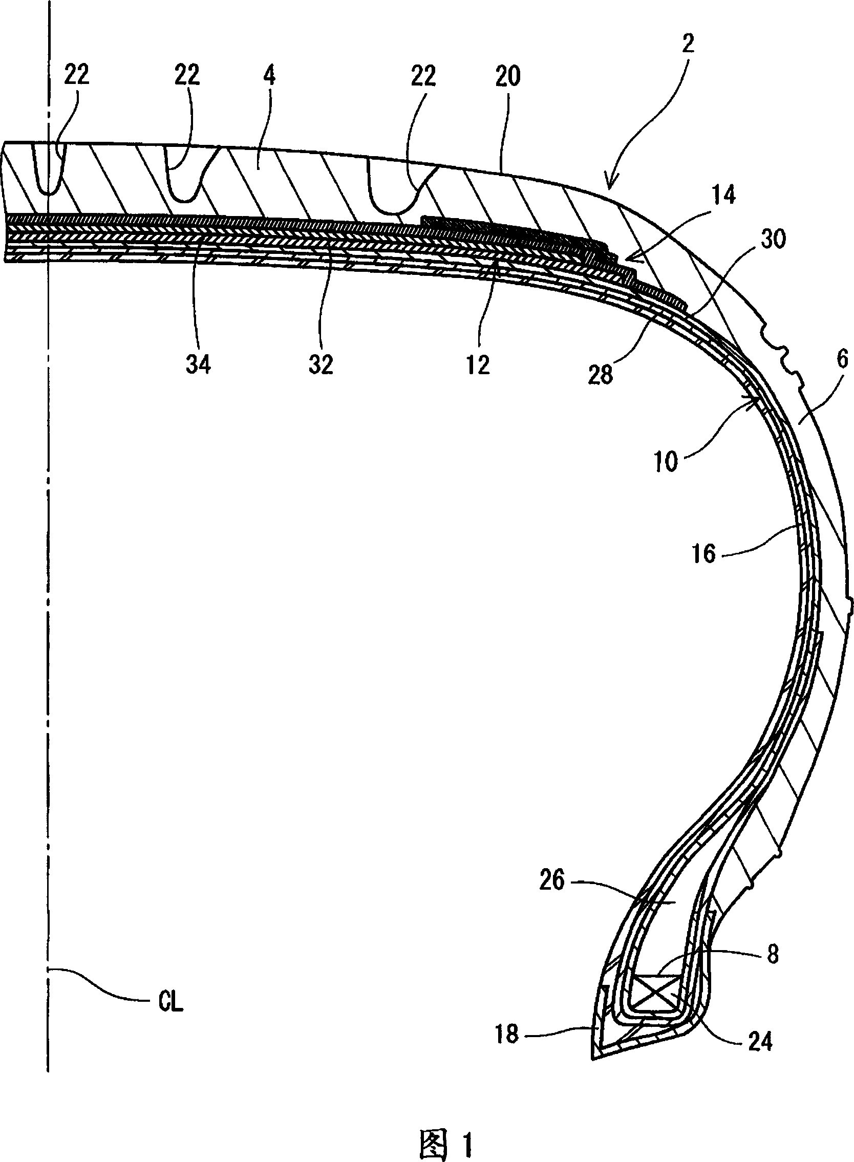
[0056]Pneumatic tires for passenger vehicles having the structures shown in FIGS. 1 to 3 were obtained. Details of the tire cap are shown in Table 1 below. In a tire, the angle formed by the belt cords of the inner belt ply relative to the equatorial plane is +24 degrees and the angle formed by the belt cords of the outer belt ply relative to the equatorial plane is -24 degrees Spend. The tire size is "205 / 50R17". The axial distance WA between the outer end of the full crown belt and the outer end of the belt is 5 mm. The distance WB between the outer end of the belt and the outer end of the edge cap was 3 mm. The axial distance WC between the outer end of the full crown belt and the outer end of the belt is 8mm. The ratio of the axial distance WD between the outer end of the full cap and the inner end of the marginal cap to the width WS of the full cap (WD / WS×100) was 17.6%.

Embodiment 6 to 9

[0058] A tire was obtained in the same manner as in Example 1 except that the axial distance WA was set as shown in Table 1 below.

Embodiment 10 and 11

[0060] Tires were obtained in the same manner as in Example 1 except that the axial distance WB was set as shown in Table 1 below.


PUM


Abstract

A tire ( 2 ) includes a belt ( 12 ) provided on a carcass ( 10 ) and a band ( 14 ) for covering the belt ( 12 ). The band ( 14 ) includes a full band ( 36 ) and a pair of edge bands ( 38 ) provided in the vicinity of a shoulder and positioned on an outside in a radial direction of the full band ( 36 ). The full band ( 36 ) has a first band cord ( 40 ) wound spirally in a substantially circumferential direction. The edge band ( 38 ) has a second band cord ( 44 ) wound spirally in the substantially circumferential direction. A modulus of the second band cord ( 44 ) is higher than that of the first band cord ( 40 ). In the tire ( 2 ), it is preferable that an outer end ( 50 ) of the full band ( 36 ) should be provided on an outside of an outer end ( 48 ) of the belt ( 12 ) in an axial direction. An outer end ( 52 ) of the edge band ( 38 ) is identical to the outer end ( 48 ) of the belt ( 12 ) or is provided on an inside thereof.

Description

[0001] This application claims priority from Patent Application No. 2005-367459 filed in Japan on December 21, 2005, the entire contents of which are hereby incorporated by reference. technical field [0002] The present invention relates to a pneumatic tire mainly mounted on a passenger vehicle. Background technique [0003] A radial tire intended for high-speed straight-line travel includes a cap ply between the tread and the belt. The band ply includes band cords wound in the circumferential direction. The band cords restrain the belt. The belt lift caused by centrifugal force in high-speed straight-line driving is controlled by the belt cord. US2005 / 0205189 (JP-A 2005-263137) has disclosed a pneumatic tire with good quietness and ride comfort. In this tire, the cap ply includes side portions located near the outer ends of the belt and a center portion located on the center in the axial direction. The side portions include cap ply cords with a high modulus. The cente...

Claims


Application Information

Patent Timeline
Patent Type & Authority Applications(China)
IPC IPC(8): B60C9/20
CPCB60C9/2204B60C2009/2261B60C9/005B60C2009/2219Y10T152/10765Y10T152/10783Y10T152/10801B60C9/00B60C9/18B60C11/00
Inventor 铃木益任
Owner SUMITOMO RUBBER IND LTD
Why Eureka
Eureka Blog
Learn More