
Form-fill-seal process

A technology of sealing bags and sealing rollers, applied in the field of suitable devices, can solve the problems of laborious initial packaging, flexibility, harmful and destructive mass production

Inactive Publication Date: 2007-06-20
TRANSDERMAL TECH & SYST TTS
View PDF10 Cites 5 Cited by
  • Summary
  • Abstract
  • Description
  • Claims
  • Application Information

AI Technical Summary

Problems solved by technology

[0010] 2. Initial packaging is a laborious process
This feature tends to have low cycle speeds, causing production bottlenecks, incurring additional cost, and the risk of damaging the patch when it is selected for packaging
[0011] 3. Cannot incorporate tear-tab into patch during primary production
Again, this requires product alignment to keep in sync and suffers from similar drawbacks to those associated with secondary pouching
[0012] 4. The process disclosed in WO 99 / 52513 relies on contact surface clamping between horizontal jaws and vertical rollers to drive material through the process as there is no separate sheet drive unit
[0013] 5. More significantly, due to the nature of the technology, the flakes will drift throughout the process
As a result, non-destructive sampling such as by weight is unreliable and all sampling must be destructive
[0014] 6. Although the process allows flexibility in choosing patch size, load composition, machine throughput, and supply reel specifications, this flexibility is detrimental in high-volume production due to human error
Tension in thin sheets leads to inaccuracies, and the process is not suitable for liquids

Method used


Image

  • Form-fill-seal process
  • Form-fill-seal process
  • Form-fill-seal process

Examples


Embodiment Construction

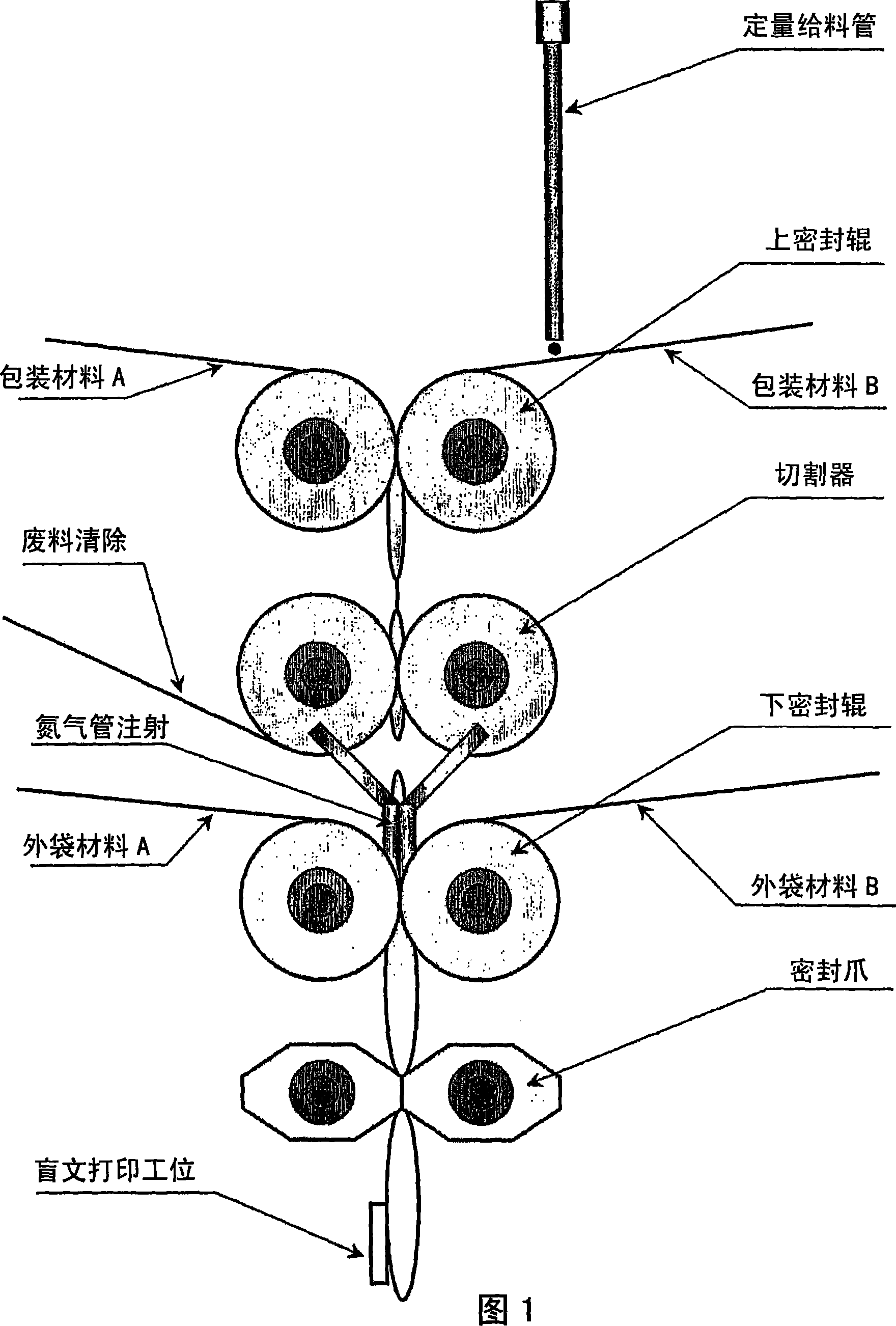
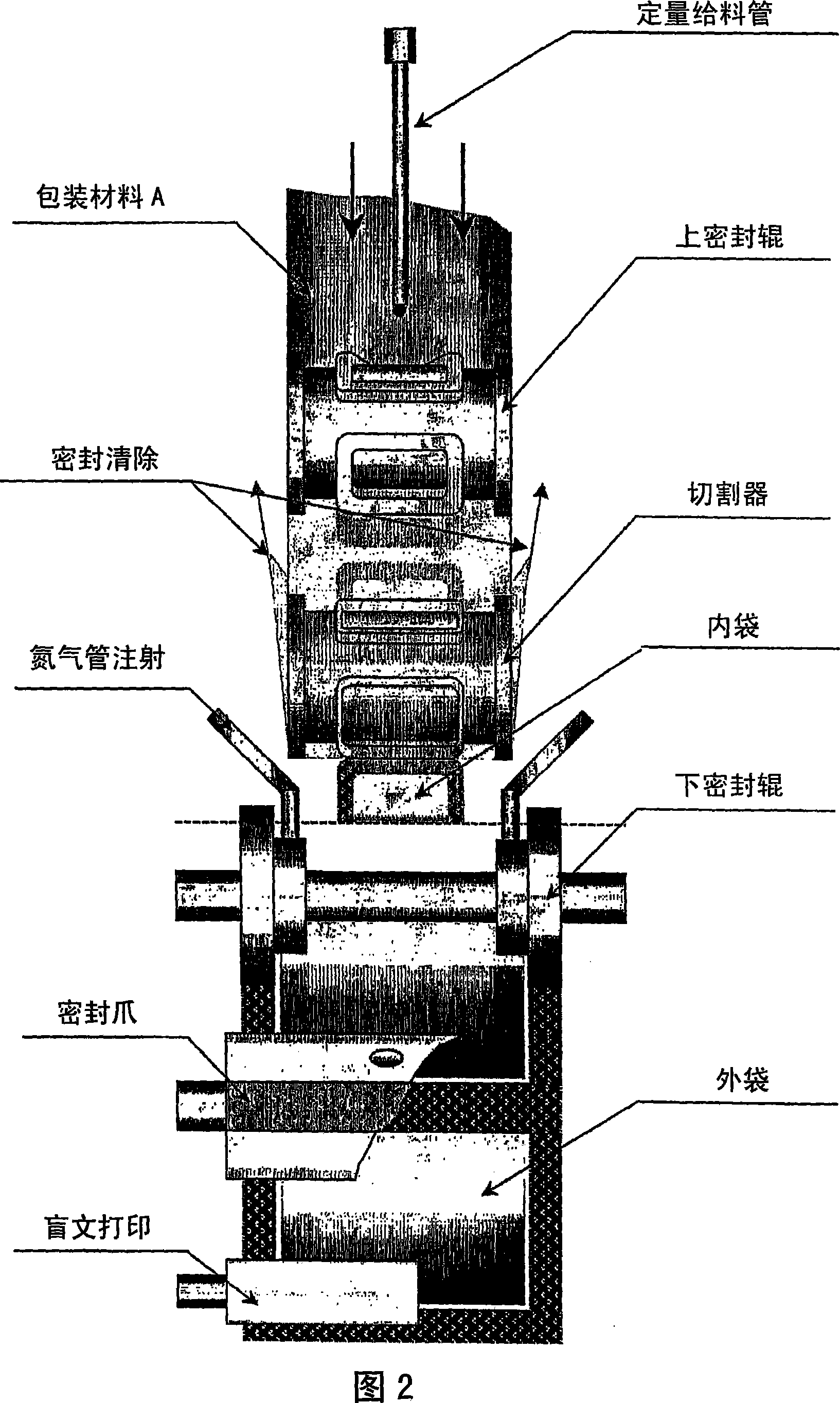
[0112] A particularly preferred embodiment of the invention is shown in Figures 1 and 2, and provides two series of pairs of opposing monolithic cylinder blocks for a continuous manufacturing process producing bags and patches. A first series of integral cylinder blocks seals together two parallel webs of material to create a storage space enclosing a selected formulation inserted between two sheets of material. The second series of integral cylinder blocks cut out sealed patch or bag templates. In the third station, the twin webs of outer bag material are drawn into twin sealing rolls, gathering one or more bags, and the sealing jaws are then used to seal the outer bag.

[0113] More specifically, pouch packaging materials A and B are fed to the upper sealing roll. In this example, a dosing tube is shown which dispenses a dose of the bag ingredient onto the packaging material B. This is for illustration purposes only and it will be appreciated that dosing may be applied to ...


PUM


Abstract

A one stage process for the preparation reservoir patches comprises feeding webs to a first pair of sealing rollers and, thence, directly to a second pair of die-cutting rollers, and preferably directly into a packaging step, thereby avoiding most operatorrelated error, and substantially increasing overall sterility and reproducibility.

Description

technical field [0001] The present invention relates to a process for forming, filling and sealing pouch products, such as depot transdermal patches, and to suitable devices for carrying out the process. Background technique [0002] Transdermal patches generally take one of two forms; matrix or depot. Matrix-type patches typically consist of an impermeable backing material that has an adhesive on one side and wherein the adhesive also includes an active material for transdermal patches. )substance. Once the patch has been applied to the skin, the active substance dissolves from the adhesive into the skin. However, such patches suffer from the dual problem of encapsulating sufficient active material in the adhesive and subsequently maintaining high levels of the active material in the adhesive without leaching into the skin. [0003] In contrast, reservoir patches have a reservoir of the active substance formed between the impermeable backing and the adhesive, which need ...

Claims


Application Information

Patent Timeline
IPC IPC(8): B65B9/02B65B51/28
CPCB65B51/28A61F2013/0296B65B9/023B65B9/02A61K9/7084Y10T156/108Y10T156/1041Y10T156/1317Y10T156/1084Y10T156/1727
Inventor 马克·鲁珀特·塔克塞缪尔·拉德克利夫·斯内登加雷思·奈杰尔·坦皮斯特
Owner TRANSDERMAL TECH & SYST TTS
Learn More