Device and method for realizing alarm clock function

An alarm clock and functional technology, applied in the electronic field, can solve the problem of adding additional hardware clock chips, etc., and achieve the effects of low power consumption, low power consumption, and low cost

Active Publication Date: 2007-06-20
HUAWEI TECH CO LTD
View PDF0 Cites 13 Cited by
  • Summary
  • Abstract
  • Description
  • Claims
  • Application Information

AI Technical Summary

Problems solved by technology

[0006] The problem to be solved by the present invention is to provide a device and method for realizing the function of the alarm clock, so as to overcome the defect that an additional hardware clock chip needs to be added when realizing the function of the shutdown alarm clock in the prior art

Method used


Image

  • Device and method for realizing alarm clock function
  • Device and method for realizing alarm clock function

Examples


Embodiment Construction

[0032] Below in conjunction with accompanying drawing and embodiment, the specific embodiment of the present invention is described in further detail:

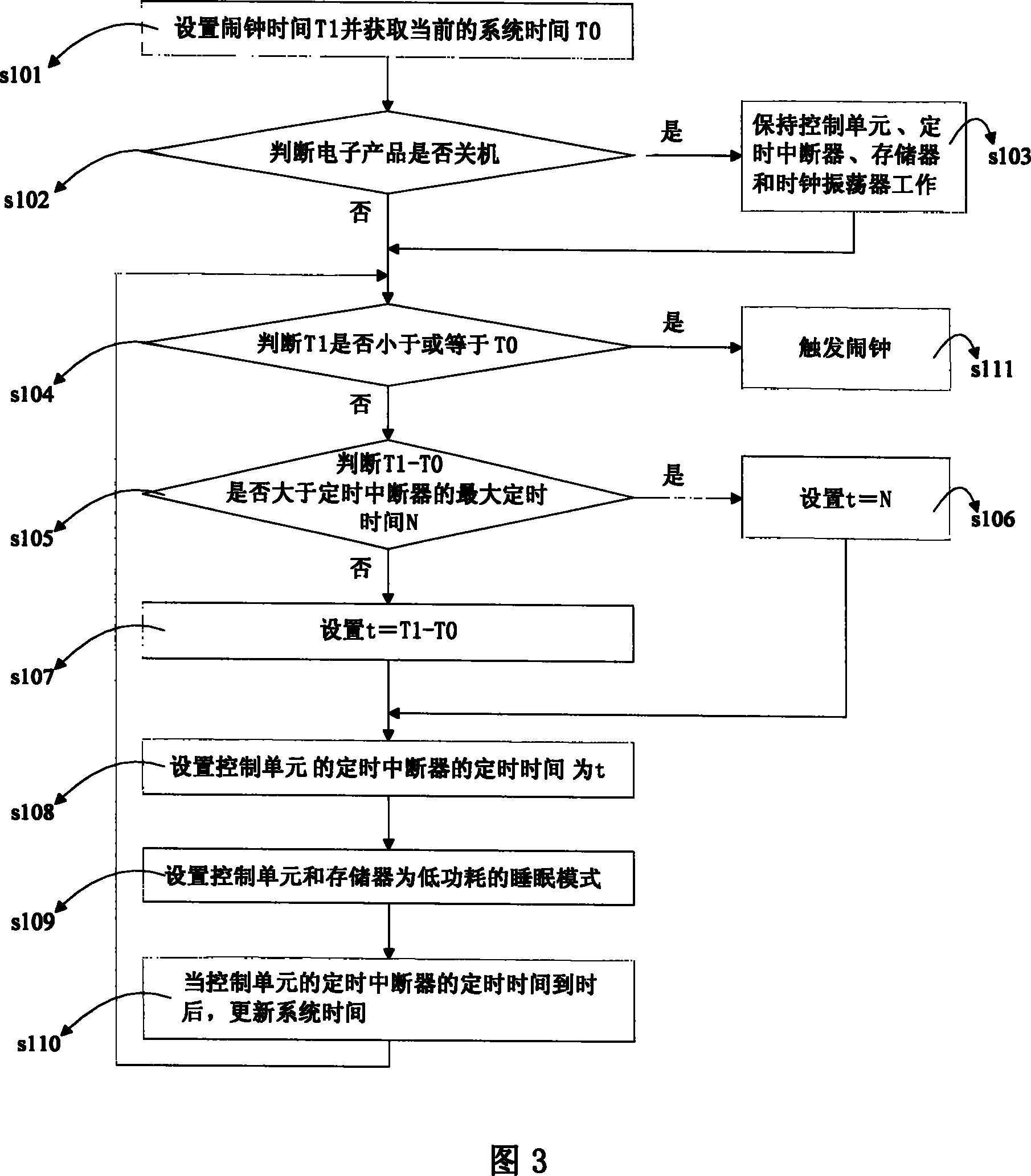
[0033] A system for realizing the alarm clock function of the present invention is shown in FIG. 2 . The system includes a power supply 21 , a memory 22 , a clock oscillator 23 , a control unit 24 and a reminder signal generating device 25 . Wherein, the control unit 24 may be a general-purpose CPU, which executes software programs and completes software functions. This control unit 24 further comprises one or more timing interrupters 26, the timing interrupter 26 is a kind of hardware circuit, the timing time is set to the timing interrupter 26 by the control unit 24, then the timing interrupter 26 starts counting, when reaching the setting After a specified time, the timer interrupter 26 initiates an interrupt to the control unit 24, and the control unit 24 processes the interrupt. However, the maximum timing time of the ge...


PUM


Abstract

A method for realizing alarm clock function includes setting a timing time of timing interruption unit by control unit according to alarm clock time, starting up timing by timing interruption unit and triggering up alarm clock when system time is on preset alarm clock time. The device used for realizing said method is also disclosed.

Description

technical field [0001] The invention relates to the field of electronic technology, in particular to a device and method for realizing the function of an alarm clock. Background technique [0002] At present, electronic products such as mobile phones and handheld devices all have a demand for an alarm clock function. When the electronic product is turned off, the main functions of the electronic product are closed without display. For example, after the mobile phone is turned off, the mobile phone is in a state of no display and unable to make and receive calls. When the electronic product is turned off, to realize the alarm clock function, a hardware clock chip is generally used now. In an actual system, the main control device writes the set value of the preset alarm clock time to the corresponding register of the hardware clock chip. After the electronic product is shut down, the hardware clock chip continues to work. When the system time and the preset alarm clock time...

Claims


Application Information

Patent Timeline
IPC IPC(8): G04G15/00G04G13/02G06F9/00G06F9/06G06F9/44
Inventor 薛林
Owner HUAWEI TECH CO LTD
Why Eureka
Try Eureka