
Detecting device for optical-fiber circuit breakage of passive light network PON system

A passive optical network, optical fiber loop technology, applied in transmission systems, wavelength division multiplexing systems, electromagnetic wave transmission systems, etc. Low volume, high mass production yield, and small volume

Inactive Publication Date: 2007-06-13
CHUNGHWA TELECOM CO LTD
View PDF0 Cites 5 Cited by
  • Summary
  • Abstract
  • Description
  • Claims
  • Application Information

AI Technical Summary

Problems solved by technology

At present, the market still mainly uses the software power-on system in the system for automatic detection, so when there is a problem with the system, it is impossible to confirm whether it is a problem with the control of the electrical system, or a problem with the optical fiber loop, which will increase the difficulty of detection, which is not good. The design needs to be improved

Method used


Image

  • Detecting device for optical-fiber circuit breakage of passive light network PON system
  • Detecting device for optical-fiber circuit breakage of passive light network PON system
  • Detecting device for optical-fiber circuit breakage of passive light network PON system

Examples


Embodiment Construction

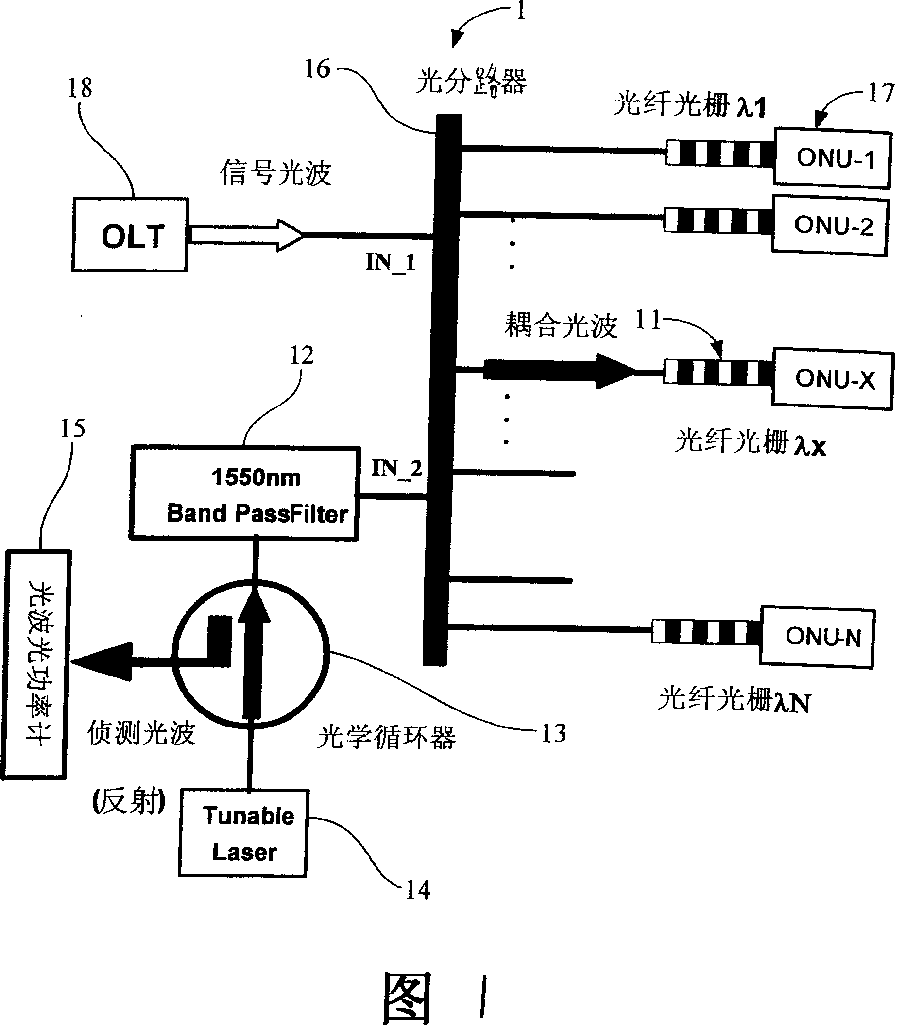
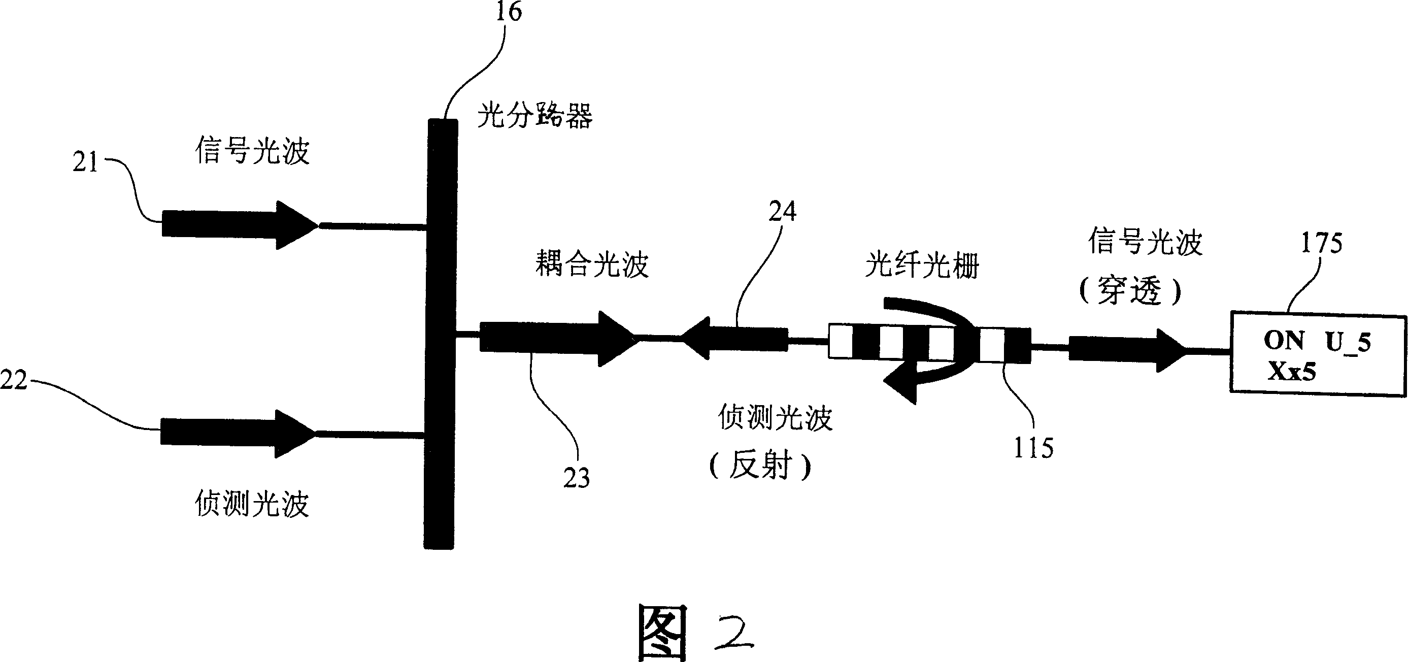
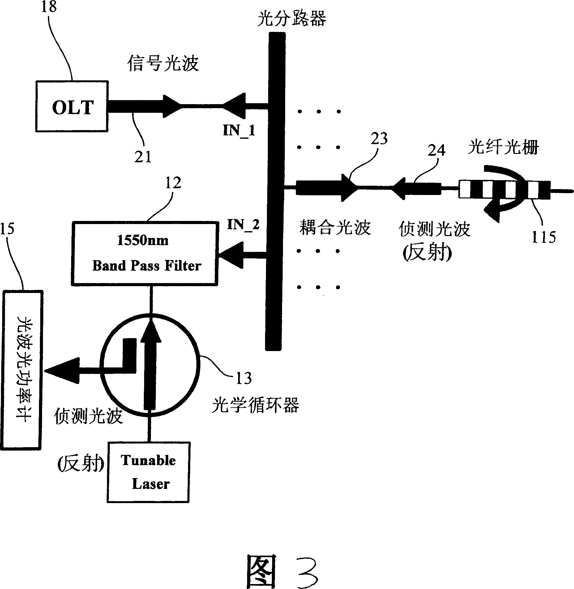
[0018] Please refer to Fig. 1, which is a schematic diagram of the structure of a detection device for a disconnection of an optical fiber loop in a PON system of the present invention. It can be seen from the figure that a detection of a disconnection of an optical fiber loop in a PON system of the present invention Device 1, comprising Fiber Bragg Grating (Fiber BraggGrating, FBG) 11, 1550nm optical band pass filter (Optical Band Pass Filter) 12, optical circulator (Optical Circulator) 13, adjustable laser (Tunable Laser) light source 14 and light wave optical power Count 15; in optical fiber transmission, the characteristics of optical reflection and transmission of fiber grating 11 combined with optical components such as optical bandpass filter 12, optical circulator 13, and adjustable laser light source 14 form a passive optical network PON system The detection device 1 for the disconnection of the optical fiber loop can judge whether the optical fiber loop is disconnecte...


PUM


Abstract

Using intensity of reflected light of sensing light wave from fiber grating, the invention determines whether there is disconnection in fiber loop, or light loss of fiber loop is too high in order to distinguish whether electric system control or fiber loop goes wrong decidedly. Using 1550nm fiber Bragg grating as main module, the device includes 1550nm light band-pass filter, optical circulator, tunable laser light source, and optical power meter of light wave. The invention is the technique for detecting disconnection of fiber loops in low cost, and replicated assembling and repeatedly uses so as to reduce maintenance cost outdoors.

Description

technical field [0001] The invention relates to a detection device for disconnection of optical fiber loop in passive optical network PON system, in particular to a low-cost and easy-to-use detection device for detection of optical fiber loop disconnection in PON system of passive optical network. Passive optical network PON system deployment, when there is a problem with the system, it can detect whether the optical fiber user circuit is disconnected and whether the optical loss of the optical fiber circuit is too large in the general computer room, clearly distinguishing between the electrical system control and the problem of the optical fiber circuit , which can greatly reduce the cost of outdoor maintenance and overhaul. Background technique [0002] With the rapid growth of the global Internet, the traditional network can no longer cope with the demand for high-speed information transmission applications caused by the communication revolution. The maturity of the optoe...

Claims


Application Information

Patent Timeline
Patent Type & Authority Applications(China)
IPC IPC(8): H04B10/08H04B10/12H04J14/02H04B10/071
Inventor 廖虹惠刘一鸣
Owner CHUNGHWA TELECOM CO LTD
Learn More