
Processing technology for high-resolution digital interface

A digital interface, high-definition technology, applied in the field of high-definition digital interface processing technology, can solve the problems of poor high-frequency characteristics, messy arrangement of core wires, low operating efficiency, etc.

Inactive Publication Date: 2007-06-06
许庆仁
View PDF0 Cites 1 Cited by
  • Summary
  • Abstract
  • Description
  • Claims
  • Application Information

AI Technical Summary

Problems solved by technology

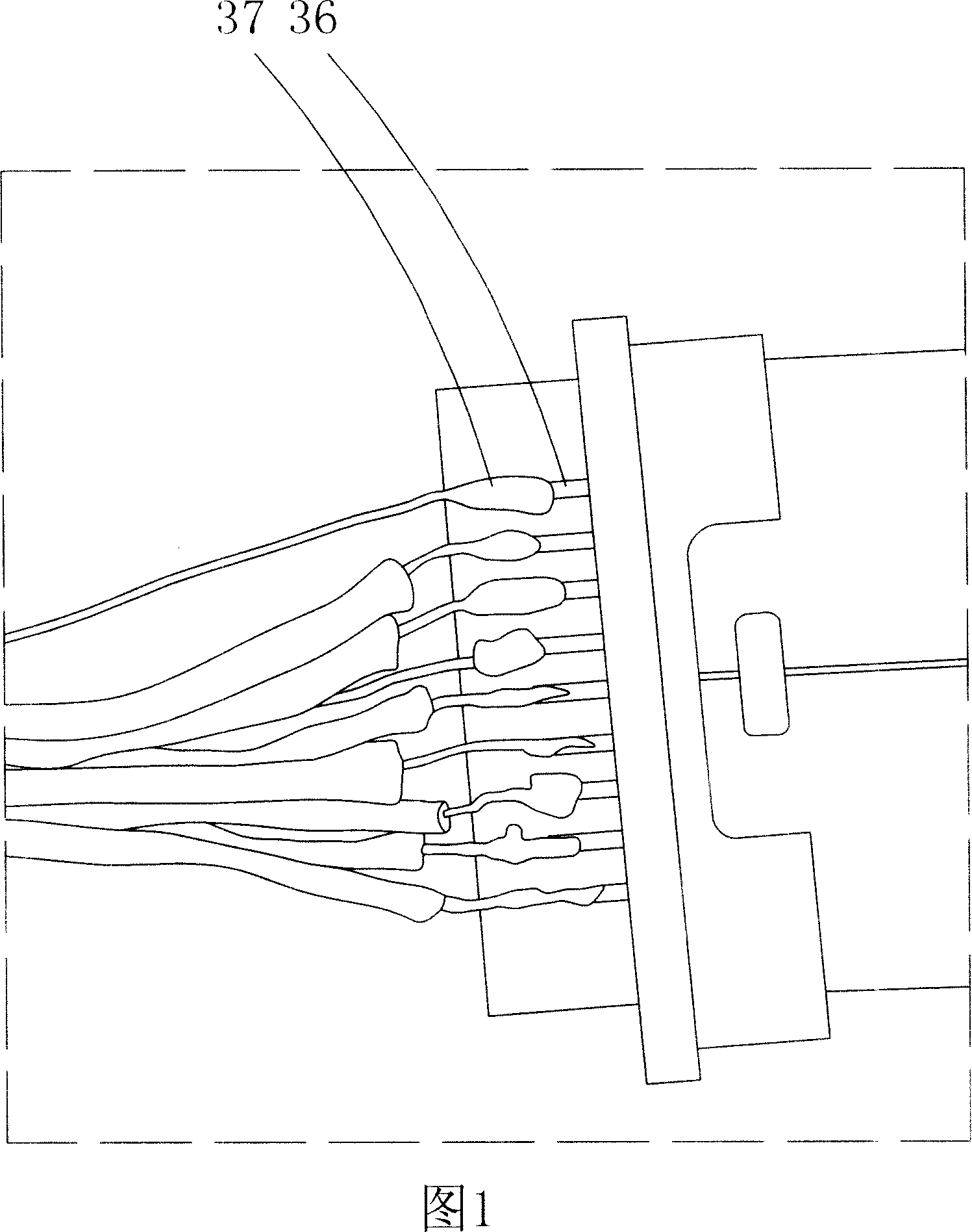
Microusb is used for signal lines between handheld devices and cameras and TVs, Dvi is used for PCs, Displayport is used for PC / TV and other related fields, currently HDMI 1.3 / Microusb / Dvi / Displayport / udi and other digital interfaces There is no structure to support the core wires. As shown in Figure 1, the core wires are arranged in a mess, signal interference will occur between the core wires, and the high-frequency characteristics are poor. When this kind of digital interface is produced, the outermost core wires are first removed. Then peel off the dense network cable, remove the aluminum foil and the inner aluminum foil, then remove the outer skin of the core wire with core stripping pliers, and finally weld the core wires to the interface one by one. The whole process is manually operated. After removing the core wire Only one core wire can be operated at a time when the sheath and welding are performed. For example, there are 19 digital TV connecting wires (four of which are ground wires, and the ground wire has no sheath, so there is no need to remove the sheath), and the core wire sheath needs to be removed. 15 times, the welding will need to be welded 19 times to complete, the work efficiency is low, the quality is unstable, and the size of each tin point 37 is different, and the distance between the terminal terminals 36 is small, it is not easy to weld, and it is easy to cause a short circuit of the connector and glue. The core is burnt, etc., the transmission performance of the connector is unstable, and the yield rate is low

Method used


Image

  • Processing technology for high-resolution digital interface
  • Processing technology for high-resolution digital interface
  • Processing technology for high-resolution digital interface

Examples


Embodiment Construction

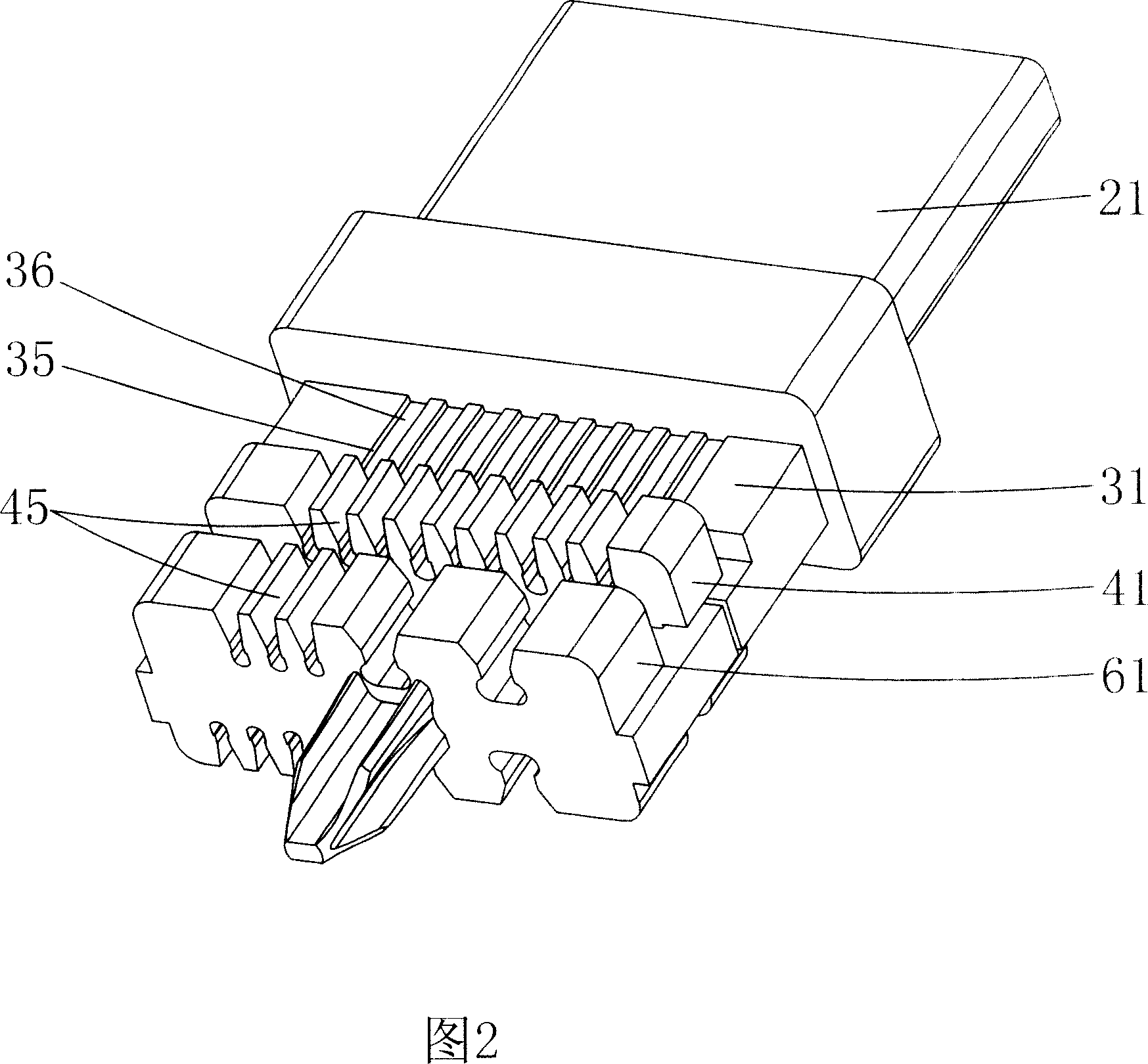
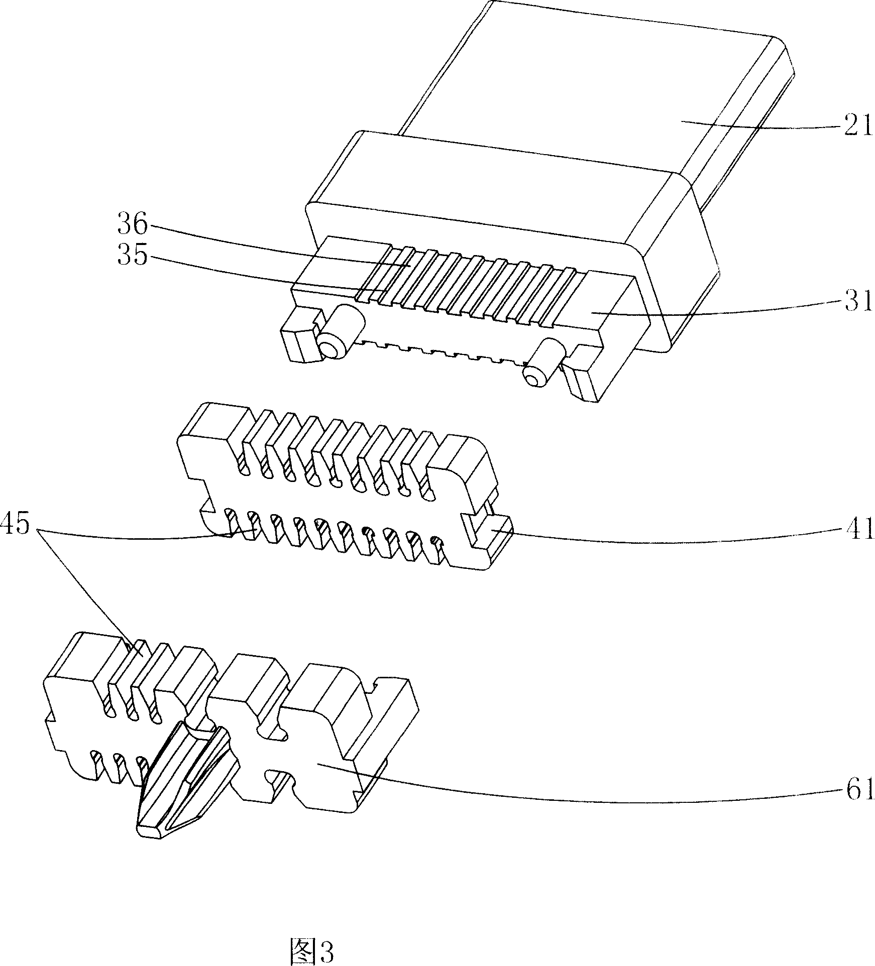
[0022] In order to further prompt the present invention, the processing technology of the present invention will be specifically described below in conjunction with specific embodiments and accompanying drawings 2 and 3 .

[0023] In the present invention, the outermost skin of the wire is first removed, then the dense mesh wire covering the core wire is stripped off, and then the aluminum foil and the inner aluminum foil are removed. It also includes the following steps:

[0024] (a): The two sides of the wire rubber plug 61 are formed with wire grooves 45, the wire grooves 45 are in the shape of a "V", and each core wire is pressed into the corresponding wire grooves 45 of the wire rubber plug 61. The tail end of the rubber plug 61 is inserted into the wire;

[0025] (b): The two sides of the puncture-type rubber plug 41 are also formed with wire grooves 45, the wire grooves 45 are in the shape of "V", and there are undercut locking positions formed in the wire grooves 45, a...


PUM


Abstract

A manufacturing process of high definition digital interface includes assembling wire rubber plug, rubber plug in stab mode, medium rubber plug and automatic welding unit on said digital interface; pressing each core wire into grooves of wire rubber plug and rubber plug in stab mode, brushing tin solder on core wires and clamping them on automatic welder for carrying out automatic welding, shining light on core wire and terminal wiring end by welder to weld core wire on terminal wiring end by melting tin solder with heating for finalizing said welding at only one time.

Description

Technical field: [0001] The invention relates to the technical field of digital interfaces, and more specifically relates to the processing technology of high-definition digital interfaces. Background technique: [0002] HDMI 1.3 / Micro usb / Dvi / Displayport / udi and other multimedia interfaces (digital interfaces) are high-frequency interfaces in the industry, (HDMI1.3c) can provide data transmission bandwidth up to 10.2Gbps, Microusb can reach 5.1Gbps, and dvi can reach 4.95 Gpbs, udi is faster, can reach 21Gpbs, HDMI 1.3 is used for handheld devices and TV cables, can transmit uncompressed audio signals and high-resolution video signals, and does not need to perform digital / analog or analog / analog before signal transmission Digital conversion can ensure high-quality video and audio signal transmission. For consumers, HDMI technology not only provides clear picture quality, but also greatly simplifies the installation of home theater systems because audio / video uses the same ...

Claims


Application Information

Patent Timeline
IPC IPC(8): H04N5/765
Inventor 许庆仁
Owner 许庆仁
Learn More