
Long-period optical fiber grating band-pass filtering method and band-pass filter for realizing the same method

A technology of fiber grating and band-pass filtering, which is applied in the field of long-period fiber grating band-pass filters, and achieves the effects of stable performance, easy batching, and high production yield

Inactive Publication Date: 2007-06-06
CHONGQING UNIV
View PDF0 Cites 11 Cited by
  • Summary
  • Abstract
  • Description
  • Claims
  • Application Information

AI Technical Summary

Problems solved by technology

[0011] The purpose of the present invention is just to propose a kind of long-period fiber grating band-pass filtering method in order to solve the difficulty in existing LPFG filter technology, and simultaneously design and realize the long-period fiber grating band-pass filter of this method

Method used


Image

  • Long-period optical fiber grating band-pass filtering method and band-pass filter for realizing the same method
  • Long-period optical fiber grating band-pass filtering method and band-pass filter for realizing the same method
  • Long-period optical fiber grating band-pass filtering method and band-pass filter for realizing the same method

Examples


Embodiment Construction

[0036] The present invention will be further elaborated below in conjunction with accompanying drawing:

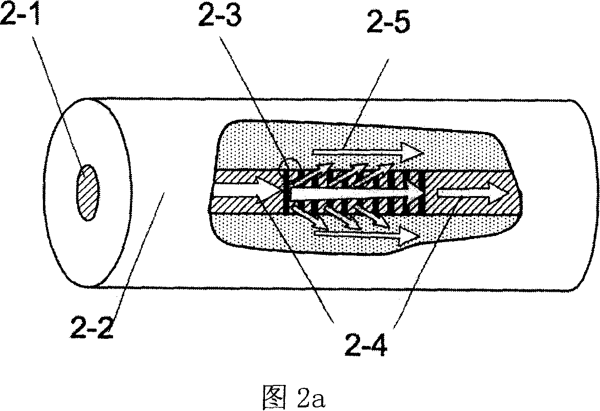
[0037] Referring to Figure 3a, the long-period fiber grating bandpass filter includes two fully matched and connected first long-period fiber gratings (abbreviated as LPFG-I) and second long-period fiber gratings (abbreviated as LPFG-II). The end of the fiber core 2-1 of the rear end face 2-6 of LPFG-I is made with a metal titanium tungsten coating as the core mode absorber 2-7, and the diameter of the core mode absorber 2-7 is 9 microns, and the fiber core 2- 1 with the same diameter. This long-period fiber grating bandpass filter is manufactured using micro-electromechanical systems (MEMS) and micro-nano manufacturing technology, see Figure 4, the process flow is as follows:

[0038] 1) Preprocessing:

[0039] Prepare a pair of matching long-period fiber gratings, take LPFG-I, and treat its rear end surface as a mirror surface;

[0040] 2) Cleaning:

[0041] Soak in ...


PUM


Abstract

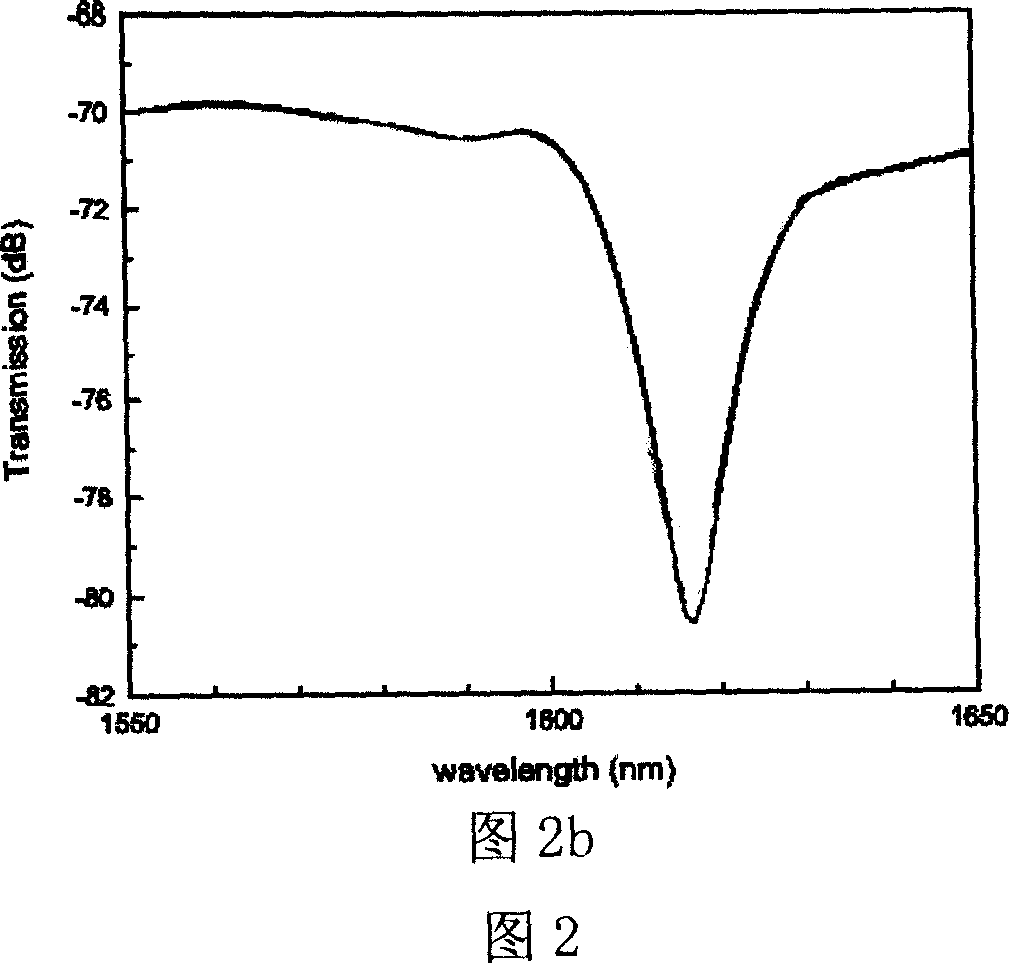
This invention discloses a kind of long-periodic optical fiber grating band filtering method , it adopts two long-periodic optical fiber grating LPFG-I and LPFG-II which mate and connect together, making mandrel absorber in the core place in the back face of LPFG-I; The light is divided into core mode and cladding mode after passing LPFG-I , the core mode is absorbed by mandrel absorber, And the cladding mode pass through the interface of two gratings, be transferred to LPFG-II and coupling reversely to the core mode in its grating area, finally returning to the core mode of LPFG-II, outputting from the back face of LPFG-II. This method has removed the routine core mode in LPFG but has made use of the cladding mode, only the light which according with the phase match conditional can pass trough the grating pair of the long-periodic optical fiber, forming a band filter. This invention keeps merit of the exist LPFG filter that no back reflecting , tuning capability is good , making up its deficiency, changing the 'band stop'type spectrum to 'bandpass' type spectrum , realizing the real long-periodic optical fiber grating band filter.

Description

technical field [0001] The invention belongs to the field of optical fiber passive devices and the technical field of micro-electromechanical systems (MEMS), and in particular relates to a long-period optical fiber grating band-pass filter. Background technique [0002] The so-called "fiber grating" is to form a periodic refractive index change in the fiber, and then purposefully control the energy exchange between the modes in the fiber, and separate a specific wavelength from light of other wavelengths to form a fiber filter , it is an important optical fiber passive device for realizing wavelength division multiplexing in optical fiber communication. [0003] A fiber grating whose period is on the order of microns is called a fiber Bragg grating (FBG for short), which is currently the most commonly used fiber filter in the field of optical communication. Its working principle is "coupling between the core mode of forward transmission and the ...

Claims


Application Information

Patent Timeline
Patent Type & Authority Applications(China)
IPC IPC(8): G02B6/34G02B6/24
Inventor 朱永符欲梅陈伟民
Owner CHONGQING UNIV
Learn More