
Nanofocus X-ray tube

An X-ray tube and X-ray technology, which is applied in the field of nano-focused X-ray tubes, can solve the problems of high equipment costs, large installations, and high costs, and achieve the effects of increasing service life, reducing equipment costs, and reducing manufacturing costs

Inactive Publication Date: 2007-05-30
COMET
View PDF0 Cites 15 Cited by
  • Summary
  • Abstract
  • Description
  • Claims
  • Application Information

AI Technical Summary

Problems solved by technology

[0006] The disadvantage of the known nanofocus X-ray tubes is that, in order to obtain an ideally smaller cross-section of the electron beams, the focus on the target requires high equipment costs, such as the installation of a large number of electromagnetic lenses
It is therefore costly and expensive to manufacture

Method used


Image

  • Nanofocus X-ray tube
  • Nanofocus X-ray tube
  • Nanofocus X-ray tube

Examples


Embodiment Construction

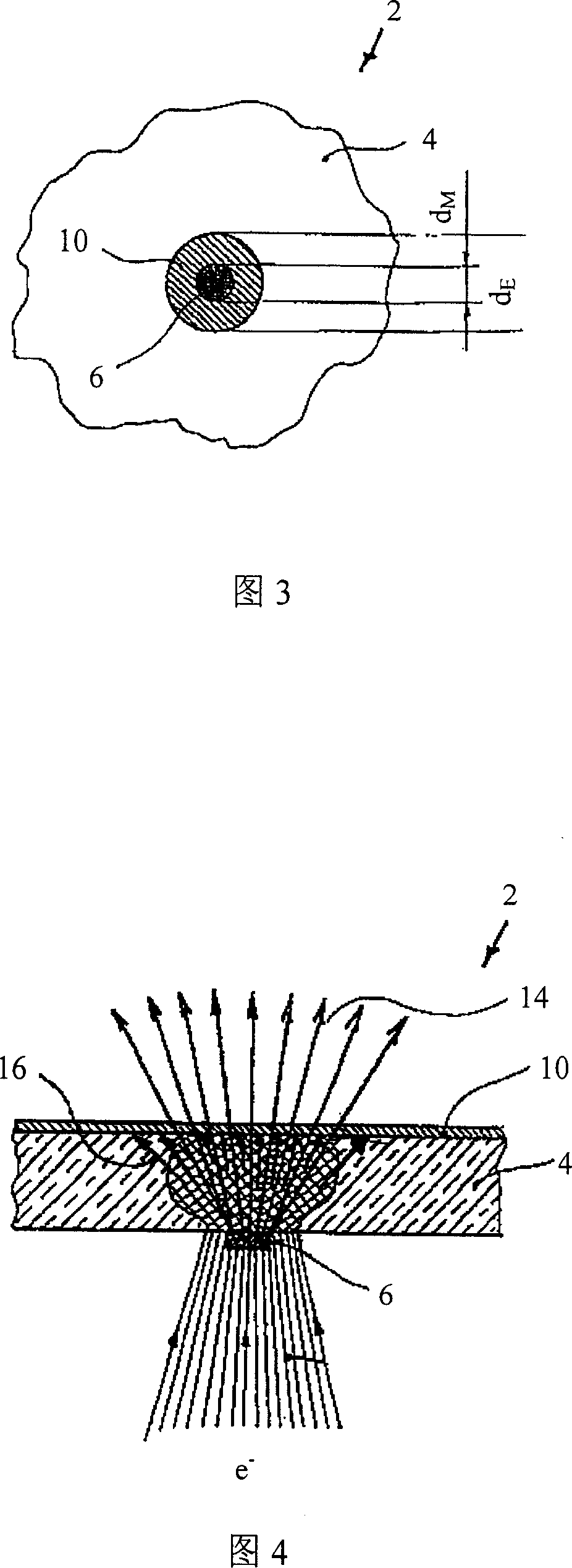
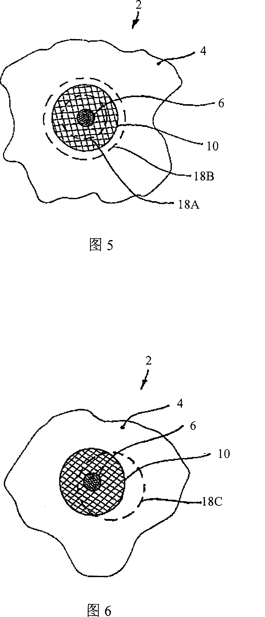
[0038] 1 shows a first embodiment of an object 2 for a nanofocus X-ray tube according to the invention, which object 2 is provided with a carrier element 4 and in this embodiment is provided with a The target element 6 on the carrier element 4, which consists of a target material, is used to emit x-rays. The carrier element 4 basically consists of a carrier material with a lower density and higher thermal conductivity, ie diamond, whose thermal conductivity is ≧20 W / (cm×K).

[0039] According to the present invention, the diamond used as the carrier material has improved electrical conductivity, and metal ions are added in this embodiment. As a result, the carrier material is made electrically conductive by the dosing, charges can be discharged from the carrier element 4 , and charging of the carrier element 4 and the object 2 is avoided.

[0040] The target element 6 consists of a material with relatively high density, in this embodiment tungsten. When shot with charged par...


PUM


Abstract

The invention relates to a nanofocus X-ray tube 20 pwovided with a target 4 and a device used for calibrating an electronic beam 28 on the target 4. According to the invention, the target 4 has at least one of target units 22, 24, 26 made of target material for emitting x-ray beam, and is composed by amicro-structuring process and a nanostructure formed on a carrier unit 4 composed of a carrier material, the nanostructure has a diameter less than 1 nm, wherein the target units 6, 22, 24, 26 only partly cover the carrier unit 4. When the X-ray tube 20 is operated, the electronic beam is selected with a cross section large than the cross sections of the target units 6, 22, 24, 26, in this way, the electronic beam 28 can entirely always irradiate on the target units 6, 22, 24, 26 all the time. According to the invention, the carrier material is diamond or contains diamonds, diamonds are added for increase conductive performance.

Description

technical field [0001] The invention relates to a nanofocus X-ray tube provided with an object and means for collimating electron beams on the object. Background technique [0002] Nanofocus X-ray tubes of the type described are generally known. It has a target and means for aligning the electron beam on the target. Nanofocus X-ray tubes are used, for example in the way shown, for high-resolution inspection of components, such as circuit boards for the electronics industry. In order to obtain a higher spatial resolution using the method shown in this diagram, electron beams are formed in a known nanofocus X-ray tube so that a focus with a diameter of ≤ 1000 nm is formed when focused on an object. [0003] In order to obtain a rather small cross-section of the electron beams, nanofocus X-ray tubes are used, which work on the principle of X-ray generation and in which Fresnel lenses are used. Using this nano-focus X-ray tube, a focus with a minimum diameter of about 40-30nm...

Claims


Application Information

Patent Timeline
Patent Type & Authority Applications(China)
IPC IPC(8): H01J35/00H05G1/00
CPCH01J2235/081H01J2235/087H01J35/08H01J35/12H01J35/116H01J2235/083
Inventor A·莱哈德
Owner COMET
Learn More