Intersegmental dephasing asymmetric six-phase permanent-magnet linear servo-actuator
A permanent magnet linear and servo motor technology, applied in the direction of electrical components, electromechanical devices, electric components, etc., can solve the problems of low product precision, large motor volume, long longitudinal length, etc., to suppress harmonic thrust fluctuations and reduce drive power , Improve the effect of running stability and reliability
- Summary
- Abstract
- Description
- Claims
- Application Information
AI Technical Summary
Problems solved by technology
Method used
Image
Examples
Embodiment 1
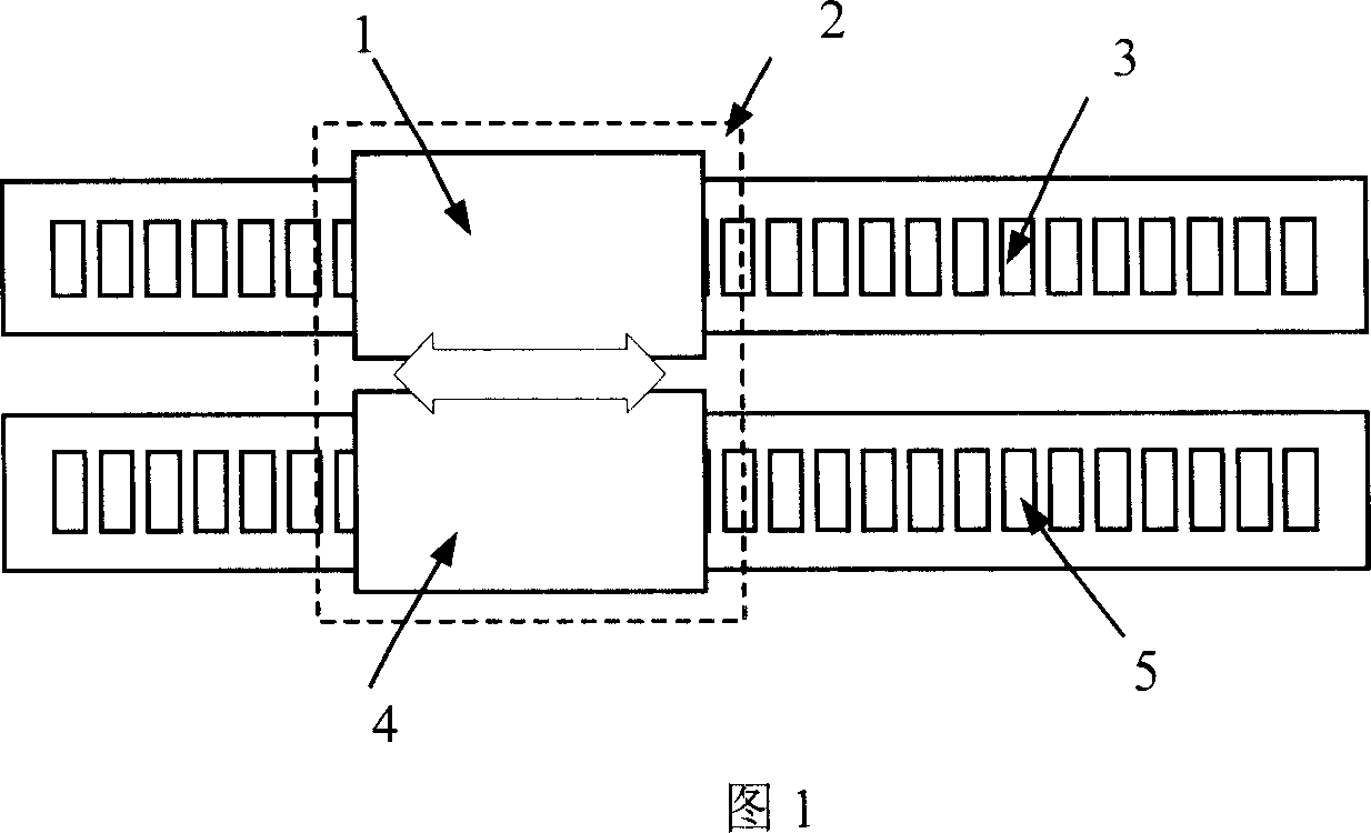
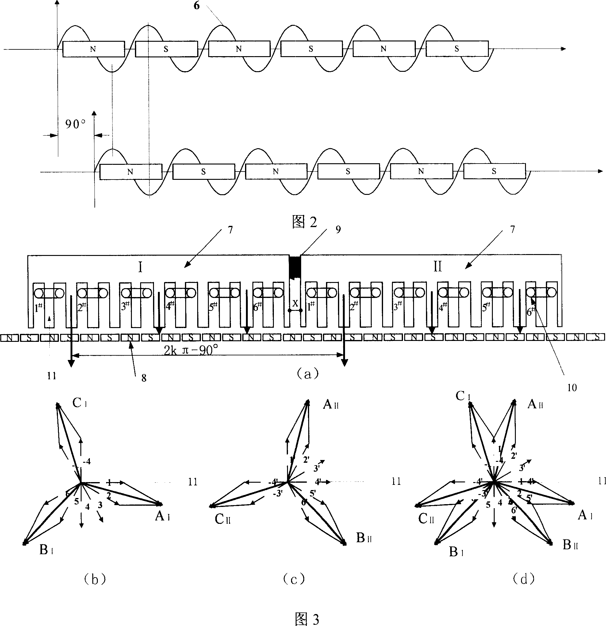
[0022] Embodiment 1: As shown in Figure 3(a), the two-unit motors adopt 12-slot 13-pole linear motors, which are installed in series. The primary 7 magnetic circuits of the two-unit motors are independent of each other, and there are non-magnetic materials 9 between the segments. The two units The phase shift interval between the corresponding winding axes of the motor is 2kπ-90°, at this time k=7, and the windings 10 of the two unit motors adopt an asymmetrical six-phase winding structure, that is, the three-phase windings of the two unit motors adopt a double-star structure, corresponding to the windings of each phase The phase difference between the axes is 30° electrical angle; the primary 7 of the two-unit motor is installed on the mobile platform 2 together, and placed above the secondary of the permanent magnet to form a whole motor.
[0023] The used lifting motor includes primary iron core, primary winding, stator yoke, permanent magnet, linear guide rail, and machine ...
Embodiment 2
[0030] Embodiment 2: The structure of the unit motor used in this example is the same as that of the unit motor in Embodiment 1. The total number of coils of the unit motor is still 6, but the installation method of the motor is different. As shown in Figure 5, the two unit motors are installed in parallel. The secondary permanent magnet magnetic circuits of the two-unit motors are independent of each other, and are installed in parallel corresponding to the 90° electrical angle of the phase shift. The primary stages of the two-unit motors are installed together on a mover platform, and the axes of the corresponding windings of the two unit motors are coincident, and are respectively placed above the secondary sides of the corresponding permanent magnets.
[0031]After the above design and installation, the windings of the two unit motors can still form the same asymmetrical six-phase winding structure as in Example 1, that is, the three-phase windings of the two unit motors ad...
Embodiment 3
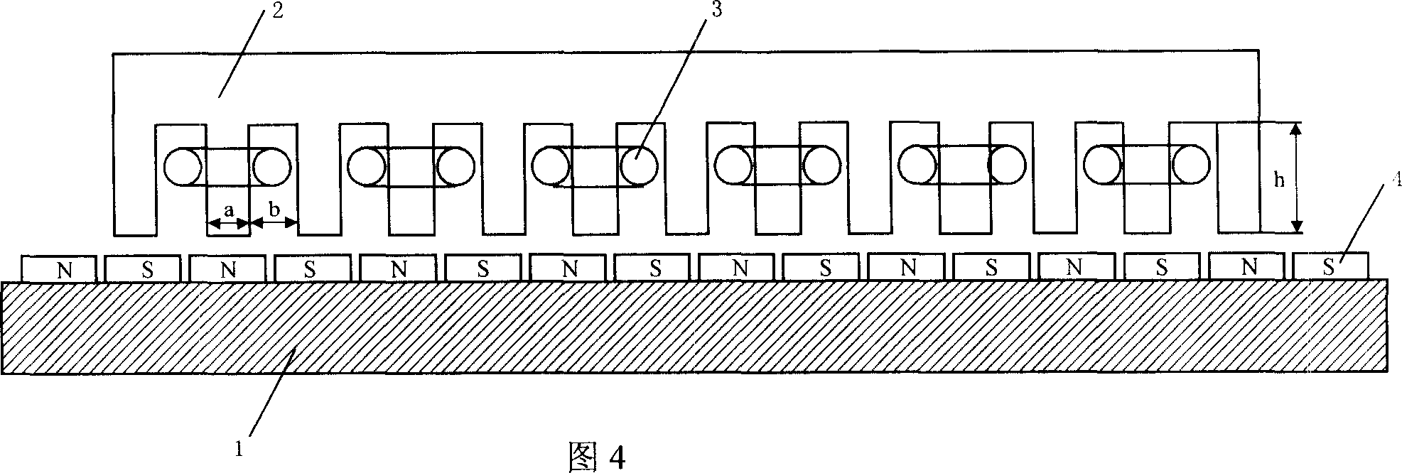
[0036] Embodiment 3: The structure of the unit motor used in this example is basically the same as that of the motor in Embodiment 1, except that the number of coils of the motor winding is different. In this example, the number of winding coils per phase is N i = 3 unit linear motor, its structure schematic diagram is shown in Fig. 6. The specific parameters of the unit motor in this example are as follows: the tooth width of the primary core a=7mm, the slot width b=8mm, the slot height h=25mm, the number of winding coils per phase of the motor N i =3, the number of motor winding phases m=3, the total number of coils of the unit motor N c =mN i =3×3=9; number of primary core slots Q=2N c = 2mN i =18, Electrical angle, equivalent slot pitch angle Electrical angle, slot distance τ y =180°±Δτ y =180°±10°; all the coils of the primary winding of the motor are divided into three symmetrical sections, each section belongs to a phase winding, that is, the relationship bet...
PUM
 Abstract
Description
Claims
Application Information
 - R&D
- Intellectual Property
- Life Sciences
- Materials
- Tech Scout
- Unparalleled Data Quality
- Higher Quality Content
- 60% Fewer Hallucinations
Browse by: Latest US Patents, China's latest patents, Technical Efficacy Thesaurus, Application Domain, Technology Topic, Popular Technical Reports.
© 2025 PatSnap. All rights reserved.Legal|Privacy policy|Modern Slavery Act Transparency Statement|Sitemap|About US| Contact US: help@patsnap.com


