
Evaporation type condenser

A technology for evaporative condensers and condenser coils, applied to evaporators/condensers, refrigerators, refrigeration components, etc., can solve the problems of reducing equipment service life, wasting energy, reducing heat transfer coefficient, etc., and achieve the goal of reducing maintenance Trouble, prolonging service life, and improving heat transfer coefficient

Inactive Publication Date: 2007-05-23
河南中轴集团有限公司
View PDF0 Cites 3 Cited by
  • Summary
  • Abstract
  • Description
  • Claims
  • Application Information

AI Technical Summary

Problems solved by technology

[0002] With the development of food, chemical, pharmaceutical and other industries, the demand for refrigeration equipment has also increased accordingly, and the evaporative condenser is one of the necessary equipment, but the evaporative condenser currently used has the speed of fouling of the condenser coil The shortcoming is that due to the fouling of the condenser coil, its heat transfer coefficient is greatly reduced, which not only wastes energy, but also the condenser is easily damaged, thus reducing the service life of the equipment

Method used


Image

  • Evaporation type condenser
  • Evaporation type condenser
  • Evaporation type condenser

Examples


Embodiment 1

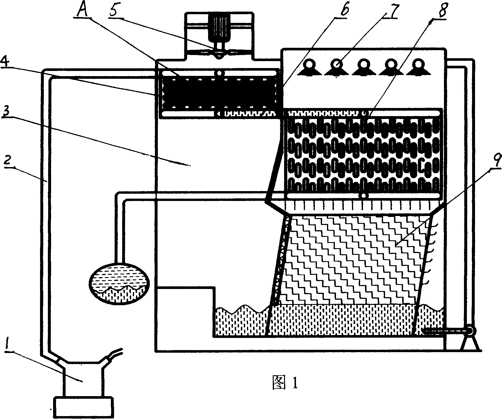
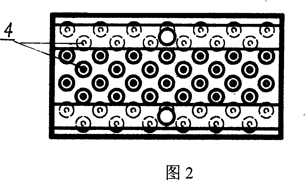
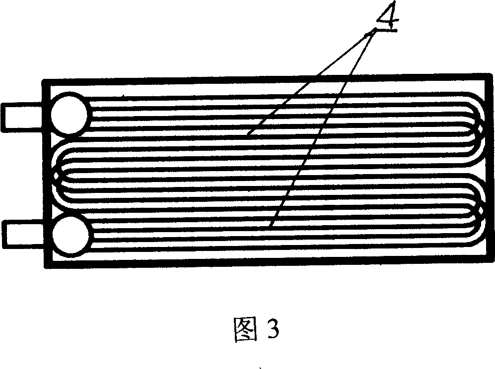
[0012] Embodiment 1: This evaporative condenser includes a compressor 1 and an evaporative condenser, and a precooling coil 4 is installed in the negative pressure chamber 3 of the evaporative condenser, and the precooling coil 4 is located at the side of the axial flow fan 5 below. The inlet end of the pre-cooling coil is connected to the compressor 1 through the conduit 2, and the outlet end is connected to the condenser coil 8 through the conduit 6. The condenser coil 8 is located under the spray water pipe 7, and the condenser coil 8 Below is the heat exchange layer 9 of the evaporative condenser made of PVC material.

[0013] The tube shape of the pre-cooling coil can be circular, elliptical or any other shape; in order to make the heat dissipation better, the outer wall of the pre-cooling coil 4 should have fins 10 .

[0014] The total length of the condenser coil 8 in the evaporative condenser described in the present invention can be identical with existing; In order ...


PUM


Abstract

An evaporative condenser comprises a compressor, evaporating condenser, precooling disk channel inside the negative pressure cavity of the evaporative condenser, precooling disk channel at the lower part of the axial fan. When strong humid warm air exhaust from the major coiler of the condenser and heat exchanging layer into the negative pressure cavity going through the gap between the pre cooling coilers with quick evaporation, reducing the temperature of the coolant inside the pre cooling coiler, greatly reducing the scaling speed at the surface of the condenser coiler of the coolant, with endurable quality and long durability.

Description

technical field [0001] The invention belongs to condensers, in particular to evaporative condensers. technical background [0002] With the development of food, chemical, pharmaceutical and other industries, the demand for refrigeration equipment has also increased accordingly, and the evaporative condenser is one of the necessary equipment, but the evaporative condenser currently used has the speed of fouling of the condenser coil The shortcoming is that due to the fouling of the condenser coil, its heat transfer coefficient is greatly reduced, which not only wastes energy, but also the condenser is easily damaged, thus reducing the service life of the equipment. Contents of the invention [0003] The object of the present invention is to provide an evaporative condenser capable of reducing the coil fouling speed in the condenser. [0004] The object of the present invention is achieved through the following technical solutions: the evaporative condenser includes a compr...

Claims


Application Information

Patent Timeline
IPC IPC(8): F25B39/04
Inventor 许春富左怀勇彭召辉
Owner 河南中轴集团有限公司
Learn More