Stapler
A stapler and staple technology, which is applied in the direction of binding, nailing staple tools, manufacturing tools, etc., can solve the problems that the stapler cannot fix the staple box guide, etc., so as to suppress the uplift and wrinkles and prevent the inability to Effects of return, good appearance and shape
- Summary
- Abstract
- Description
- Claims
- Application Information
AI Technical Summary
Problems solved by technology
Method used
Image

Examples
Embodiment 1
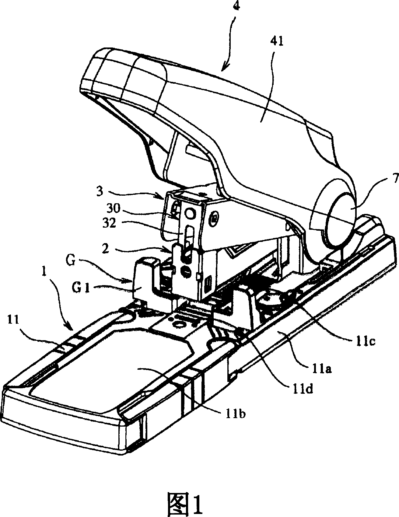
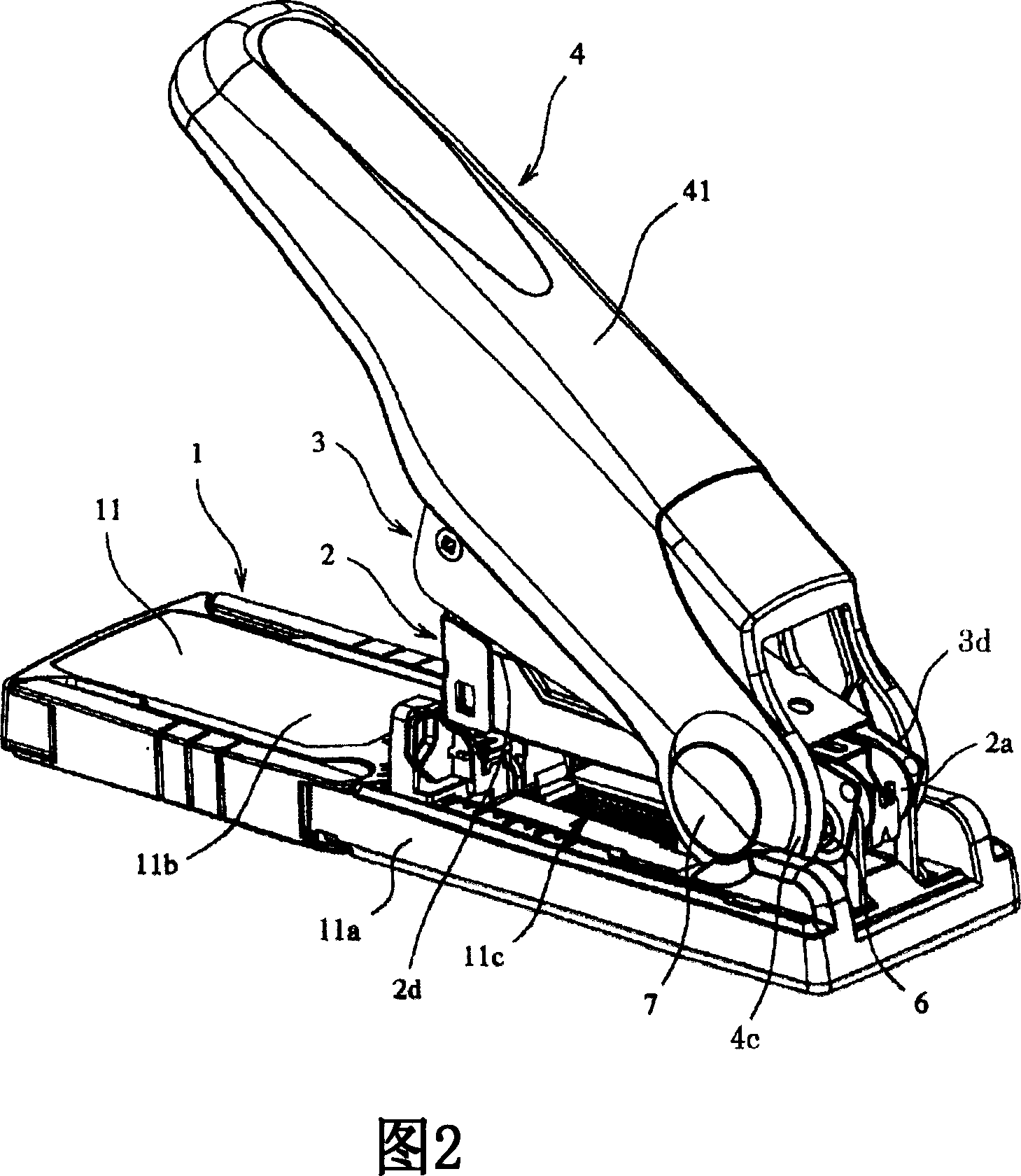
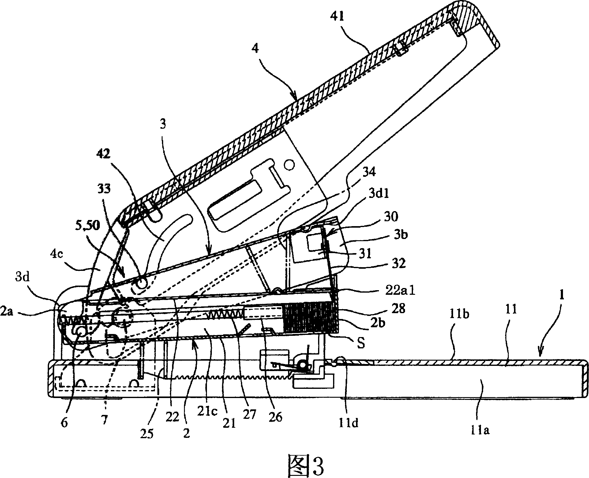
[0080]As shown in FIGS. 1 and 2, a stapler according to a first embodiment of the present invention includes a base member 1, a staple case 2 in which staples S (see FIG. Staples S stored in the driver unit 30 to bind the bundle of paper (not shown), the outer handle 4 for applying the operation force for binding the bundle of paper to the driver unit 30 through the inner handle 3, and the inner handle 3 for An interlocking mechanism 5 interlocking with the external handle 4 (see FIG. 3 ). The outer surface (ie, the upper surface and the side surface) of the outer handle 4 is covered with a handle cover, that is, a resin cover 41 .
[0081] Referring to FIG. 3 together, the base member 1 is a base for rotatably supporting the rear end 2a of the nail cartridge 2 and the rear end 3d of the inner handle 3 by the first support member 6 using the same shaft, and also utilizes The second support member 7 rotatably supports the rear end 4c of the outer handle 4 . The base member 1 ...
Embodiment 2
[0133] Fig. 14 is a perspective view of a stapler according to a second embodiment of the present invention, and Fig. 15 is a longitudinal sectional view of the stapler. In Figs. 14 and 15, reference numeral 1 denotes a base member. A binding stand 11 on which a bundle of paper is placed is formed on the front side of the base member 1 , and a magazine guide 11 e and a handle support plate 11 f stand at the rear end of the base member 1 . The cartridge 2 and the inner handle 3 are rotatably supported by the first support member 6 provided in the cartridge guide 11e. Furthermore, the outer handle 4 for operating the inner handle 3 is rotatably supported by the second support member 7 provided in the handle support plate 11f.
[0134] The staple cartridge 2 has a space in which the connected staples S are stored, and a push-out portion 28 is formed at the front end of the staple cartridge 2 . Further, a push rod 26 for pushing the connected staples S toward the push-out portion ...
Embodiment 3
[0159] FIG. 21 is a perspective view of a stapler according to a third embodiment of the present invention, and FIG. 22 is a longitudinal sectional view of the stapler. Descriptions of features substantially the same as those of the stapler according to the first and second embodiments are omitted.
[0160] According to the third embodiment, the base 1 a of the base member 1 made of metal is covered with the base covering member 60 made of synthetic resin. Accordingly, the staple groove 11 d is provided and fixed on the cartridge guide 11 e provided under the base cover member 60 .
[0161] That is, as shown in FIG. 23, the cartridge guide 11e is a metal member having a U-shaped cross section and has standing walls 61 having a large height on both sides of one end (rear end) thereof. Also, a cartridge guide 11e is fixed on the upper surface of the base 1a in the longitudinal direction. The first supporting member 6 (see FIG. 22 ) supporting the nail box 2 and the inner handl...
PUM
 Abstract
Description
Claims
Application Information
 - R&D
- Intellectual Property
- Life Sciences
- Materials
- Tech Scout
- Unparalleled Data Quality
- Higher Quality Content
- 60% Fewer Hallucinations
Browse by: Latest US Patents, China's latest patents, Technical Efficacy Thesaurus, Application Domain, Technology Topic, Popular Technical Reports.
© 2025 PatSnap. All rights reserved.Legal|Privacy policy|Modern Slavery Act Transparency Statement|Sitemap|About US| Contact US: help@patsnap.com