


Quick Research
Generate reliable direction feasibility study reports for your R&D in just a few steps.

Technical Q&A
Discover and master advanced knowledge NOW. Basics, ideas, possibilities, all at once.

Find Solutions
As an expert in R&D theories, this can generate solutions to your technical problems instantly.

Evaluate Feasibility
Analyze your overall solution with one click, know your potential R&D risks in advance.

Monitor Landscape
Get weekly tech updates, stay abreast of the latest tech innovations and key insights.
Sweeping apparatus workable at condition of electrification in high voltage
A cleaning device and high-voltage electrified technology, which is applied in the direction of cable installation device, cable installation, electrical components, etc., can solve the problems such as cleaning cannot be realized
- Summary
- Abstract
- Description
- Claims
- Application Information
AI Technical Summary
Problems solved by technology
Method used
Image

Examples
Embodiment Construction
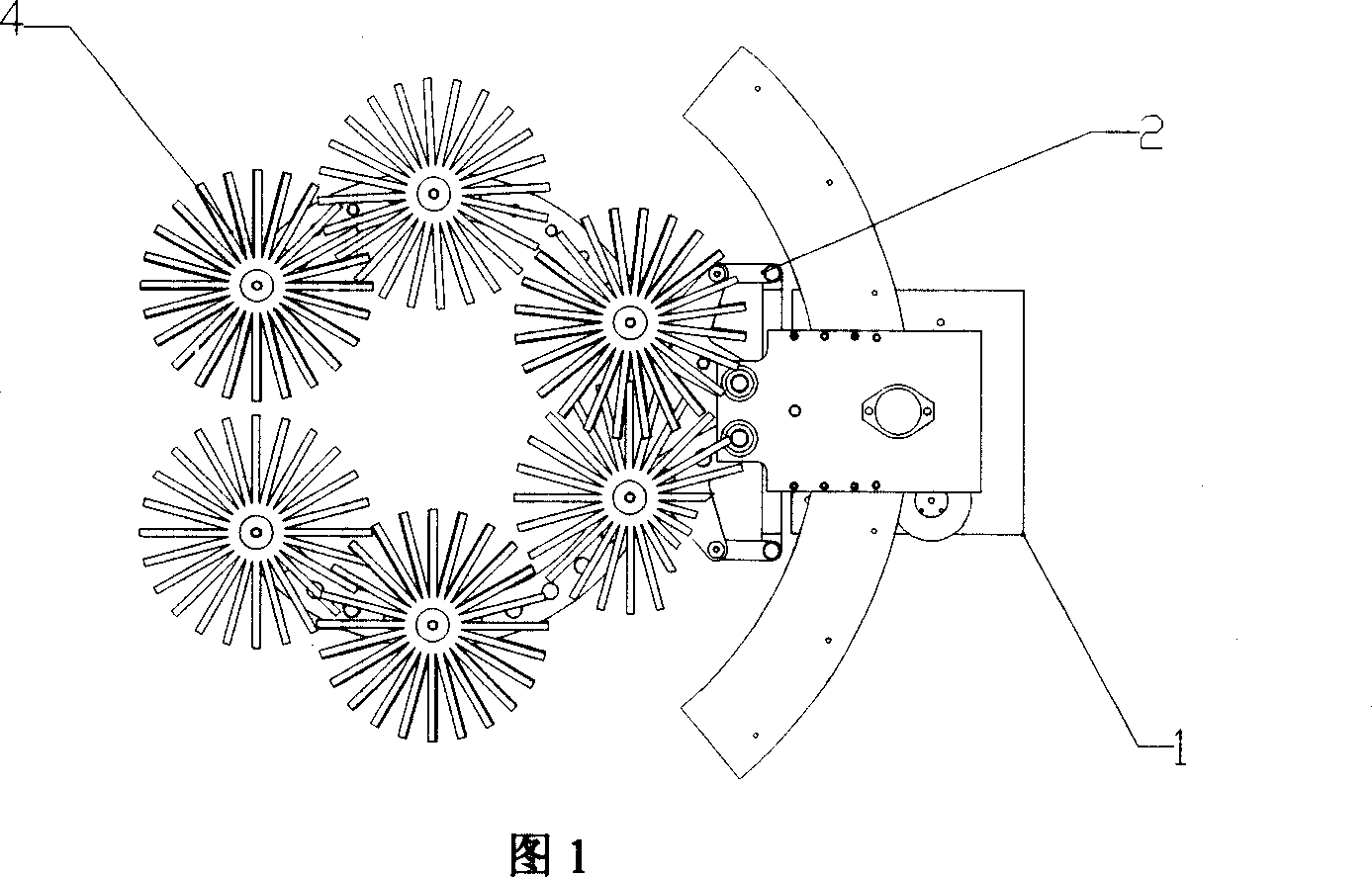
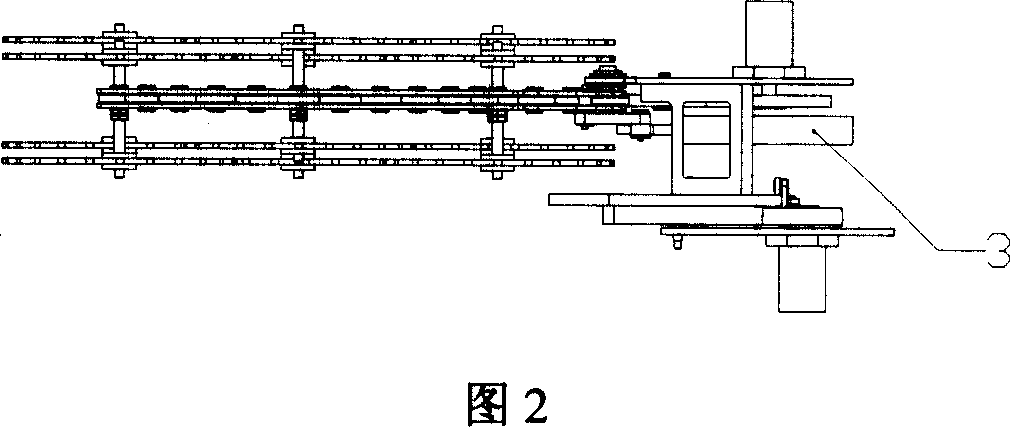
[0018] As shown in Figures 1 and 2, this embodiment includes: a rotary table 1, an opening and closing push rod 2, a linear oil cylinder 3, and a cleaning arm 4. The linear oil cylinder 3 is arranged on the cleaning arm 4, and one end of the opening and closing push rod 2 is connected to the linear oil cylinder 3 are connected, one end is connected with the cleaning arm 4, the linear cylinder 3 drives the opening and closing push rod 2, and the opening and closing push rod 2 drives the cleaning arm 4 to rotate, and drives the hydraulic motor of the rotary table 1 to transmit the rotating power to the connected brush , the brush rotates to clean the dust on the porcelain bottle.
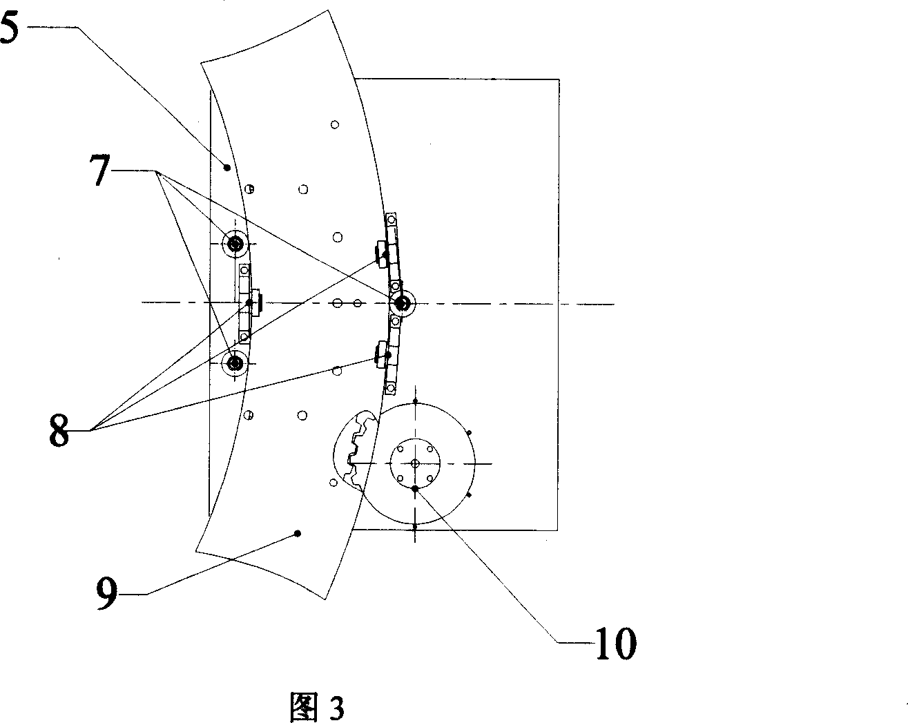
[0019] As shown in FIGS. 3 and 4 , the rotary table 1 includes: a bottom plate 5 , a lower bearing support 6 , a side bearing support 7 , an upper pressure bearing 8 , a rotating platform 9 , and a power transmission mechanism 10 .
[0020] Base plate 5, as the support of the whole device;
[0021] T...
PUM
 Abstract
Description
Claims
Application Information
 - R&D Engineer
- R&D Manager
- IP Professional
- Industry Leading Data Capabilities
- Powerful AI technology
- Patent DNA Extraction
Browse by: Latest US Patents, China's latest patents, Technical Efficacy Thesaurus, Application Domain, Technology Topic, Popular Technical Reports.
© 2024 PatSnap. All rights reserved.Legal|Privacy policy|Modern Slavery Act Transparency Statement|Sitemap|About US| Contact US: help@patsnap.com