Circuit breaker
A circuit breaker and moving contact technology, applied in the direction of protection switch operation/release mechanism, etc., can solve the problems of grid plate setting space and configuration block number limitation, circuit breaker breaking performance impact, stop pin breakage and other problems
- Summary
- Abstract
- Description
- Claims
- Application Information
AI Technical Summary
Problems solved by technology
Method used
Image
Examples
no. 1 example
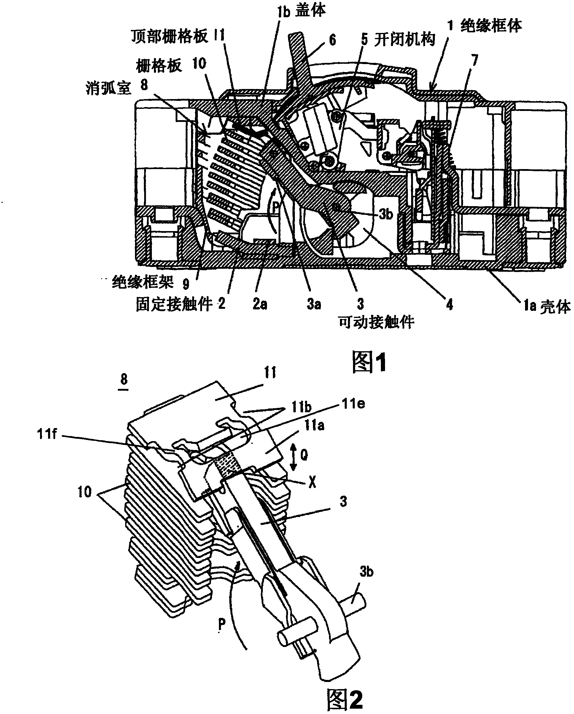
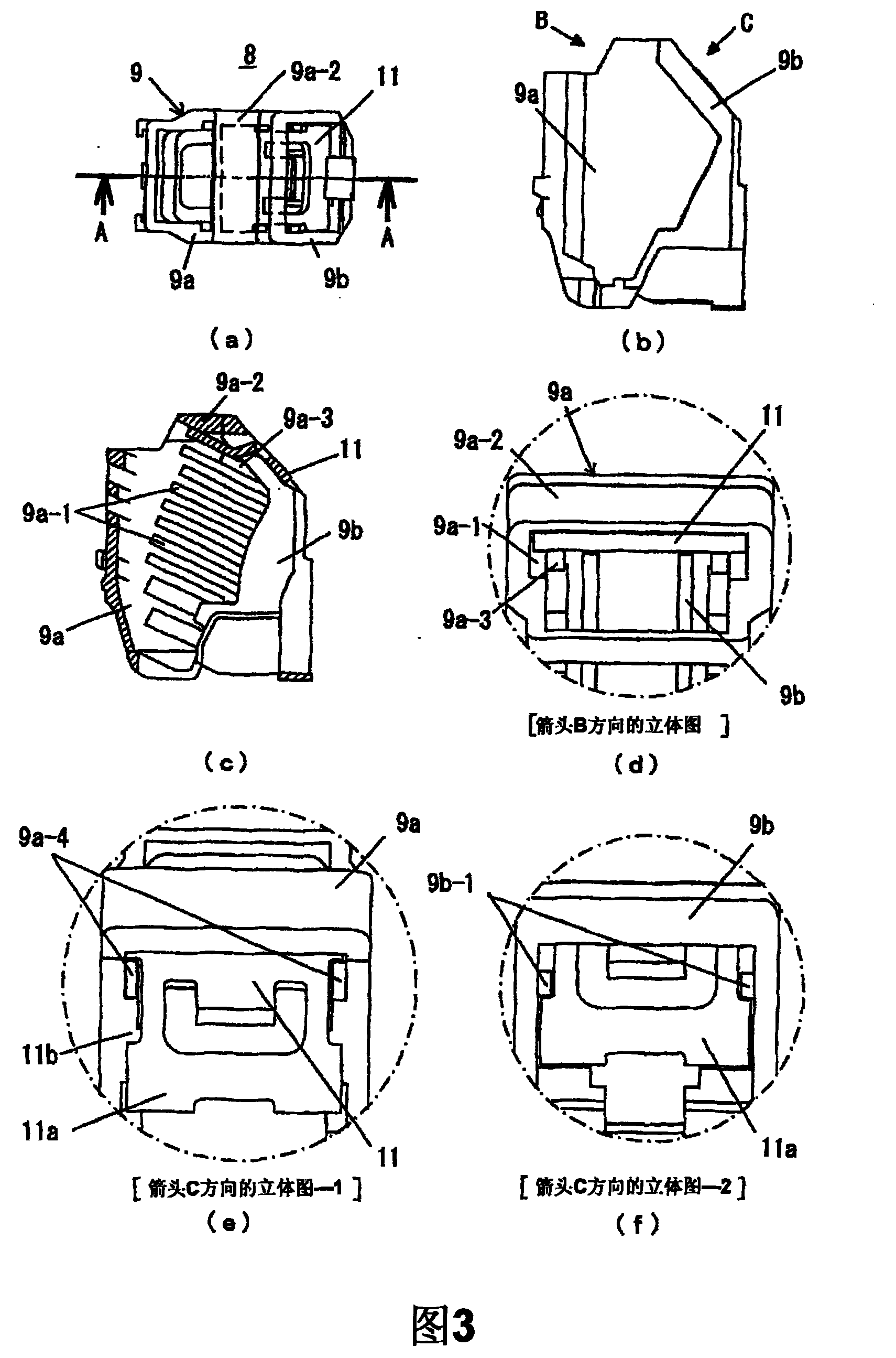
[0031] exist Figure 1 ~ Figure 4 Among them, the symbol 1 represents the insulating frame (resin molded case) of the circuit breaker composed of two separate structures of the case 1a and the cover 1b, and the symbol 2 represents the fixing of the main circuit terminal which also serves as the power supply side. The contact, the symbol 2a represents the fixed contact, the symbol 3 represents the rotary movable contact, the symbol 3a represents the movable contact, the symbol 3b represents the rotary shaft of the movable contact 3, and the symbol 4 represents What is the contact piece holding the movable contact piece 3, the number 5 indicates the toggle link type (togglering) opening and closing mechanism connected with the contact piece 4, the number 6 indicates the opening and closing operation handle, and the number 7 It represents a thermal overcurrent extraction device, and the number 8 represents the arc suppression chamber arranged in front of the movable contact 3 alo...
no. 2 example
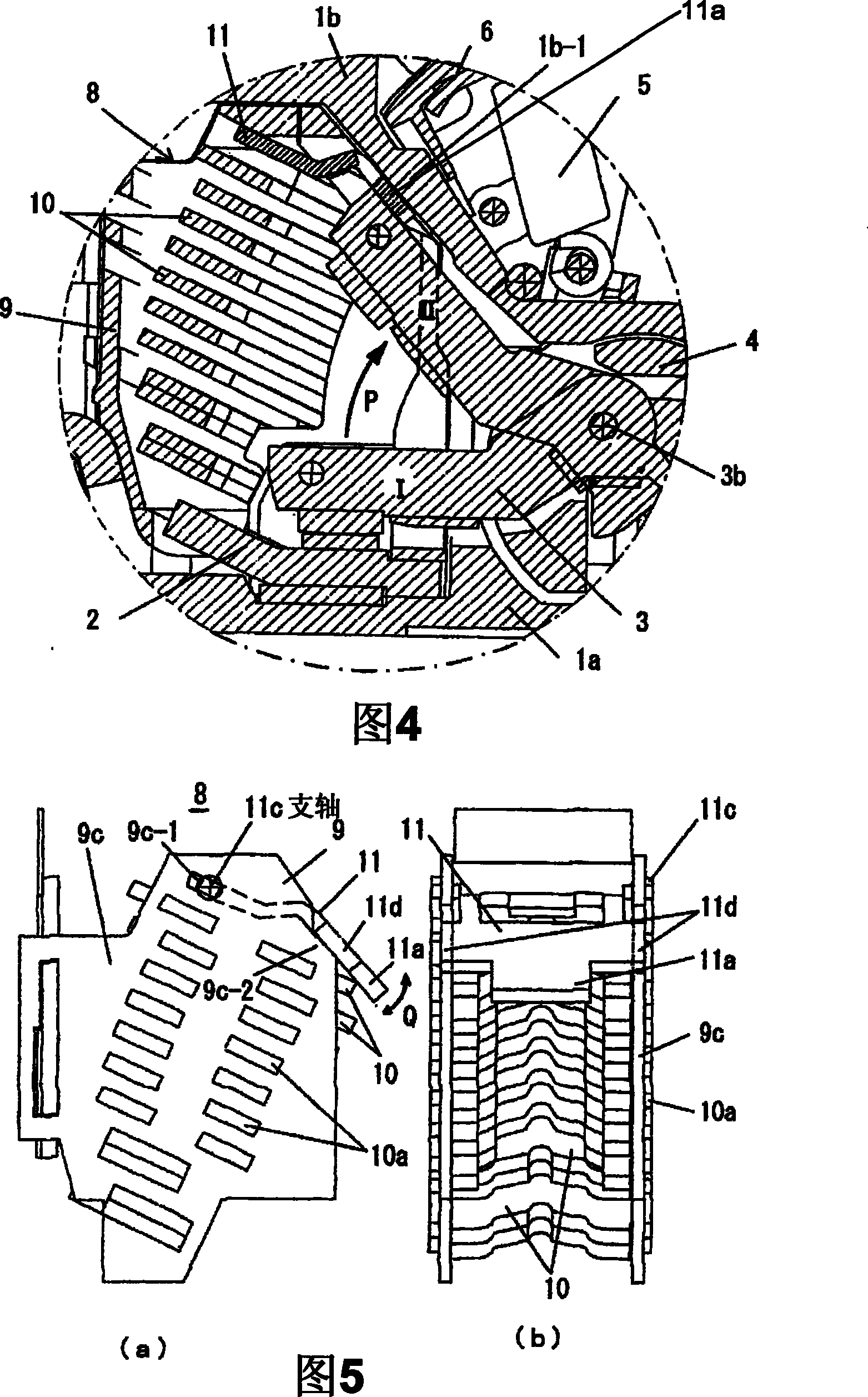
[0044] Second, use Figure 5 (a) and (b) demonstrate the Example of this invention. In this embodiment, for the top grid plate 11 held on the top of the insulating frame of the isolation chamber 8, a support shaft 11c protruding to the left and right sides is formed at the front end thereof, and a lateral support shaft 11c is formed at the rear side thereof. Engagement ears 11d whose edges protrude to the left and right sides. On the other hand, on the insulating frame side of the isolation chamber 8, on the top of the left and right side walls 9c, a bearing hole 9c-1 for inserting the above-mentioned support shaft 11c is formed through, and at the same time, the rear upper end surface of the side wall 9c is It is made as an inclined surface on which the ear portion 11d of the above-mentioned top grid plate 11 is sandwiched so that in this position, the collision portion 11a at the rear end protrudes from the back surface of the desolation chamber 8 . In addition, except the...
PUM
 Abstract
Description
Claims
Application Information
 - R&D
- Intellectual Property
- Life Sciences
- Materials
- Tech Scout
- Unparalleled Data Quality
- Higher Quality Content
- 60% Fewer Hallucinations
Browse by: Latest US Patents, China's latest patents, Technical Efficacy Thesaurus, Application Domain, Technology Topic, Popular Technical Reports.
© 2025 PatSnap. All rights reserved.Legal|Privacy policy|Modern Slavery Act Transparency Statement|Sitemap|About US| Contact US: help@patsnap.com


