
Coil with a contact sleeve for electrical connection

A technology of electrical connection and coil, which is applied in the direction of conductive connection, permanent deformation, connection and coil, etc. It can solve the problems of high cost and complexity of winding wire connection, achieve reliable positioning and avoid manufacturing errors.

Active Publication Date: 2007-04-18
SEW-EURODRIVE GMBH & CO KG
View PDF3 Cites 4 Cited by
  • Summary
  • Abstract
  • Description
  • Claims
  • Application Information

AI Technical Summary

Problems solved by technology

The disadvantage is also that the connection of the winding wires is very expensive and complicated

Method used


Image

  • Coil with a contact sleeve for electrical connection
  • Coil with a contact sleeve for electrical connection
  • Coil with a contact sleeve for electrical connection

Examples


Embodiment Construction

[0032] The invention will now be described in detail with reference to the accompanying drawings.

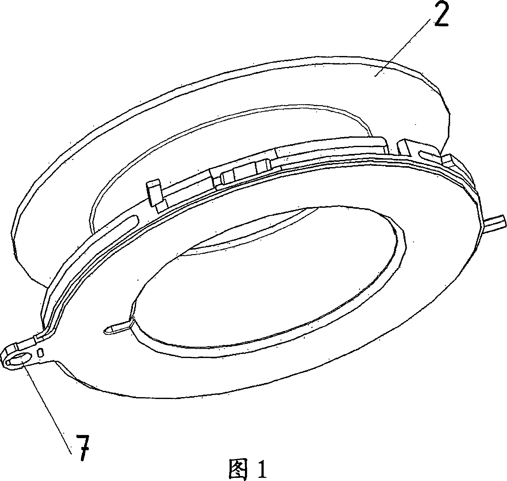
[0033] FIG. 1 shows a coil carrier 2 . The coil carrier can advantageously be produced as a plastic injection-molded part and has a holder 7 as fastening for the outgoing cable.

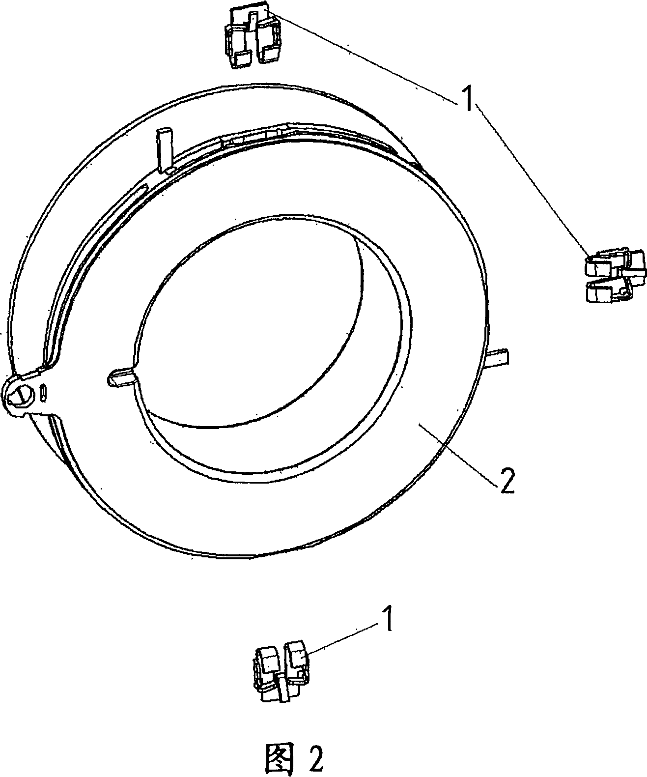
[0034] FIG. 2 shows three sleeves 1 which can be inserted into the coil carrier at three points on the outer circumference.

[0035] 12 and 13 show the detailed structure of the sleeve 1 .

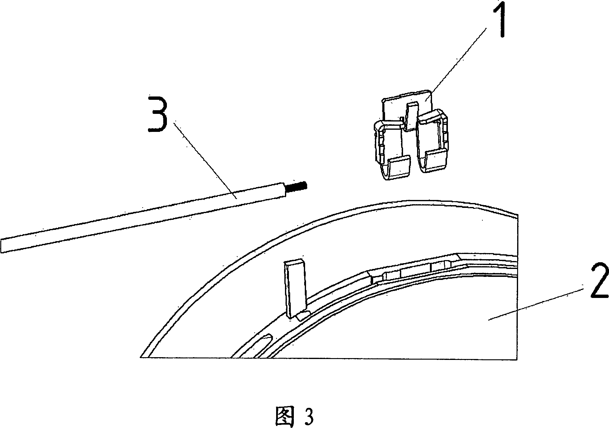
[0036] In Fig. 3 is shown a cable 3, comprising conductive litz wires and insulation, which can be inserted into the lower part of the sleeve 1 before the sleeve can be inserted into said coil support.

[0037] Three cables 3 are shown in FIG. 4 , which are connected to the sleeve 1 before the sleeve is inserted into the coil support 2 .

[0038] FIG. 5 shows an enlarged view of the cable 3 connected to the sleeve 1 , whereas FIG. 12 shows an enlarged view of the sleeve 1 itself without the cable. The left bend...


PUM


Abstract

The coil has a coil former (2) provided with a channel defined between 2 side flanges and / or a pocket for reception of a winding wire, which is electrically connected to a sleeve, in turn electrically connected to a conductor or filament of an electrical cable, the electrical connections provided by deformable tongue sections of the sleeve with subsequent soldering. A first deformable tongue section of the sleeve is used for guidance of the winding wire, a second deformable tongue section acting as a fixing tongue for providing the connection with the winding wire and a third deformable tongue section used for soldering to the cable conductor or filament.

Description

technical field [0001] The invention relates to a coil, a brake and a motor. Background technique [0002] Coil supports for coils wound with winding wire are known. [0003] From DE 3613294 a brake coil (FIG. 4, reference number 6) is known with a neutral lead, which brake coil can be used as a brake for an electric motor. The disadvantage here is that production is complex and expensive. What is important here is that every additional connection of the winding wire entails outlay and costs in production. [0004] Known from DE7923585U1 is a connection of wires in which the winding wire of the coil must be wound several times around the rod-shaped end (page 4, paragraph 3, lines 4-5, "wrapping (herumschlingen)"), Then (brazing) welding must be performed. This is very complicated and expensive. [0005] From DE 3407758 A1 a hook on a connector part is known which is provided for protection against pulling out (E2, page 9, line 11). This has the disadvantage that the co...

Claims


Application Information

Patent Timeline
Patent Type & Authority Applications(China)
IPC IPC(8): H02K5/22H01F5/02H01F5/04H01R4/18H01R13/41
CPCH01R4/187H01F5/02H01F5/04H01R13/41
Inventor P·亨利希G·弗勒尔兴各L·克里基J-P·郎布兰G·许勒尔
Owner SEW-EURODRIVE GMBH & CO KG
Learn More