
Maximum power tracing method for solar power system and solar power device

A maximum power tracking, solar power technology, applied in battery circuit devices, circuit devices, systems that store electrical energy, etc., can solve the problems of difficult real-time adaptation of the system, increased probability of misjudgment of the maximum power point, and insufficient accuracy, and achieves improved Tracking response speed, circuit and multi-functionality, the effect of improved usability

Inactive Publication Date: 2007-04-18
孙民兴
View PDF7 Cites 40 Cited by
  • Summary
  • Abstract
  • Description
  • Claims
  • Application Information

AI Technical Summary

Problems solved by technology

Its inspection and calculation procedures are complicated and time-consuming
Often rapid changes in sunlight or temperature make it difficult for the system to fully respond in real time, resulting in an increase in the probability of misjudgment of the maximum power point and affecting the efficiency of the solar system in obtaining electrical energy
[0008] (2) The illuminance or temperature of the sun may change within milliseconds, and the inspection and calculation procedures of the maximum power tracking of the known technology are prone to errors, which will reduce the correctness of the maximum power adjustment of the system
[0009] (3) The inspection and calculation circuit in the known technology is too complicated, and its accuracy is often not enough for the external harsh operating environment
[0015] (2) Advanced solar system charging adopts multi-stage discharge and pulse charging discharge, which requires additional components and control mechanisms, resulting in more complex solar system circuits
[0017] (1) For loads that require a constant current, such as solar LED street lights, the brightness is often dimmed gradually due to the voltage change of the battery, and the same brightness cannot be obtained
[0018] (2) For loads that require constant current, such as solar LED street lights, LED street lights are often not designed to be in the brightest state due to battery voltage
[0020] (4) Often the battery still has power, often because the voltage is too low to drive the load

Method used

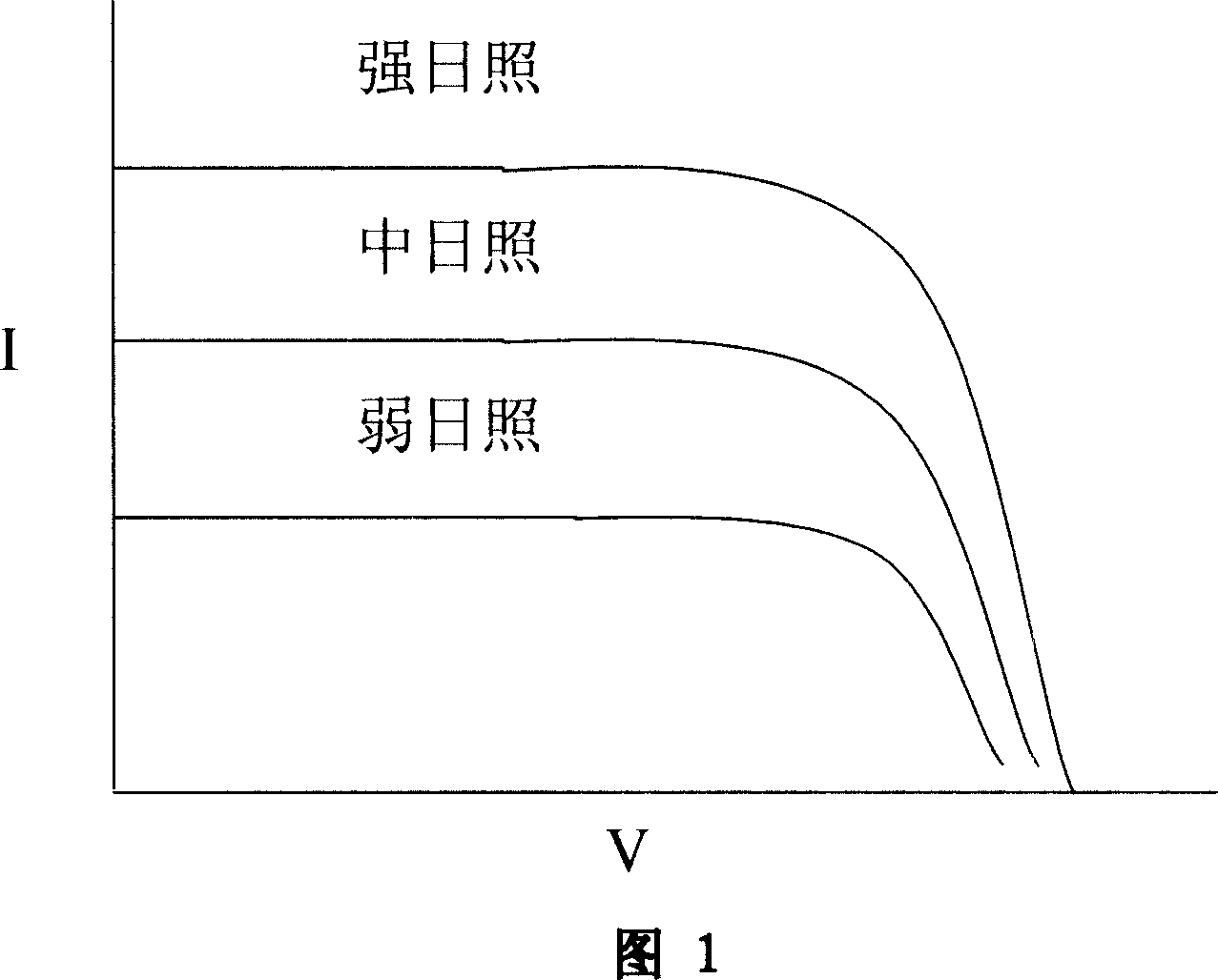
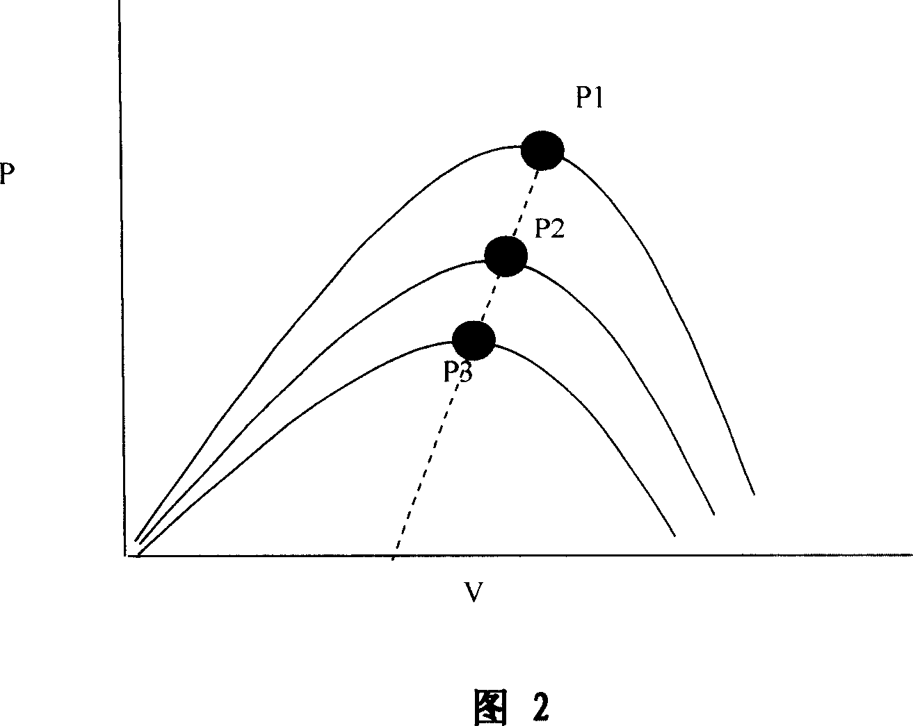
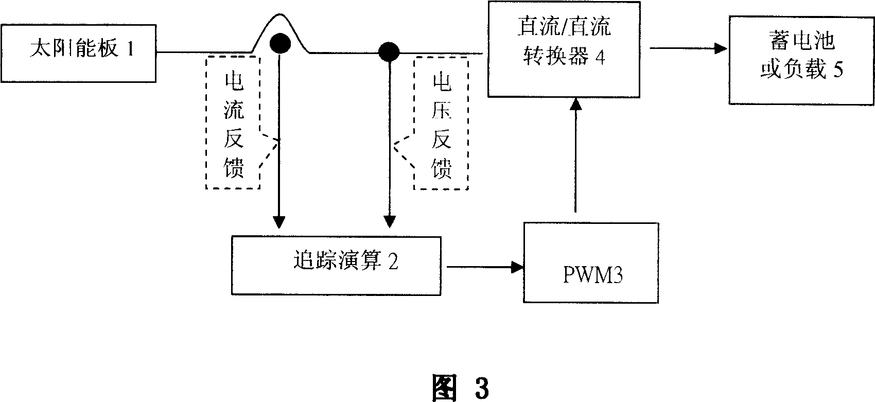

Image

  • Maximum power tracing method for solar power system and solar power device
  • Maximum power tracing method for solar power system and solar power device
  • Maximum power tracing method for solar power system and solar power device

Examples


Embodiment Construction

[0070] As shown in Figure 4, the basic composition of the device for implementing the "Peter Energy Disturbance Observation Solar Maximum Power Tracking Method" includes:

[0071] (1) Solar panel 6: It is an array of solar cells, which are connected in series and parallel according to the required output voltage and current, and convert photoelectricity into electrical energy under various sunlight intensities.

[0072] (2) Instantaneous power type supercapacitor 7: refers to a capacitor with low internal resistance and high capacitance, which can be used as a temporary storage of electric energy. In the steady state in a dynamic balance mode, the output power of the solar panel is received and the output power is sent to the DC / DC converter. The instantaneous power type supercapacitor may be a supercapacitor of metal oxide electrodes, a carbon material supercapacitor, a polymer supercapacitor, a hybrid type ultracapacitors, aluminum electrolytic capacitors or similar high cap...


PUM


Abstract

The invention discloses a maximum power tracking method for a solar energy power supply system and the solar energy power supply unit thereof, relating to solar power generation technical field. And the method tracks the maximum power of the solar energy system by dynamic balancing. According to the method, it adds in intelligent charging-discharing mechanism to form an intelligent coordination solar energy device, comprising at least a solar panel, super capacitor, DC / DC buck-boost converter, pulse width modulation driver, storage battery, logic controller and load; and the method is characterized in that an instant power type super capacitor is connected between the solar panel and the DC / DC buck-boost converter to act as an energy dynamic balancer; it converts the electric energy produced by the solar panel into capacitor type electric energy to make the maximum power calculation, able to largely simplify calculation program, improving tracking calculation real-timeness and reliability and raising solar energy system efficiency. And the invention can be widely applied to solar LED lamps, and solar energy lamps, especially solar energy street lamps, solar traffic signal lamps, solar energy engineering lamps, etc.

Description

technical field [0001] The invention relates to a maximum power tracking method using a solar (photovoltaic) power generation system and a device for implementing the method, belonging to the technical field of solar (photovoltaic) power generation and supercapacitors. Background technique [0002] Solar energy is the most common energy source that can be miniaturized. From the perspective of use, solar energy has (1) safety, reliability, no noise, and no pollution; (2) no greenhouse gases such as CO2 are produced; (3) the required energy is available everywhere, no need to consume fuel and no mechanical rotating parts; (4) maintenance Simple, long service life; short construction period, flexible scale; (5) unattended, and no need to erect transmission lines; (6) low energy costs in remote areas; (7) easy to combine with buildings and other advantages. [0003] However, solar energy is a non-ideal renewable energy source, and the power generated by the sunlight environment...

Claims


Application Information

Patent Timeline
IPC IPC(8): H02J7/35H02J15/00
CPCY02E70/30
Inventor 张荣锜孙民兴孙实钧
Owner 孙民兴
Learn More