
Backlight unit

A technology of backlight unit and light source unit, which is applied in optics, nonlinear optics, instruments, etc., and can solve problems such as brightness reduction

Inactive Publication Date: 2007-04-18
LG ELECTRONICS INC
View PDF1 Cites 2 Cited by
  • Summary
  • Abstract
  • Description
  • Claims
  • Application Information

AI Technical Summary

Problems solved by technology

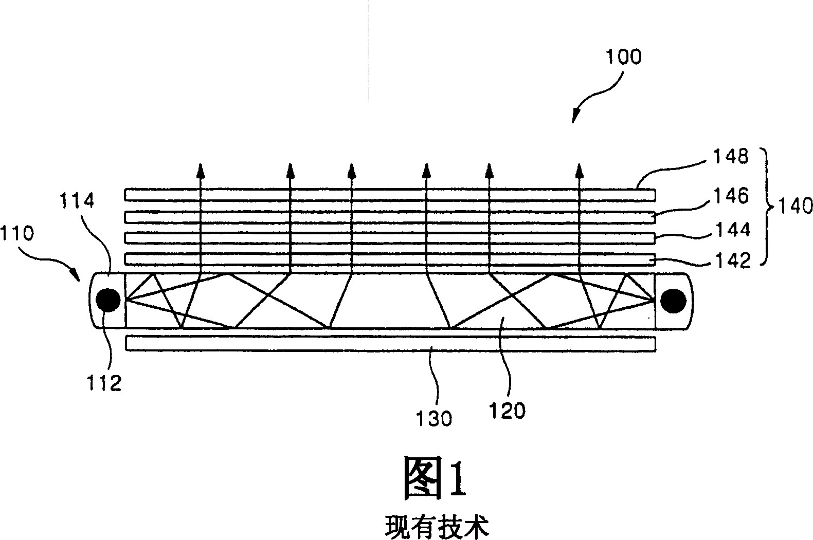
[0018] In this BLU, the incident surface of the light guide plate 120 is perpendicular to the upper surface of the light guide plate 120, so when the light from the light source 112 passes through the incident surface of the light guide plate 120, the brightness is significantly reduced.

Method used


Image

  • Backlight unit
  • Backlight unit
  • Backlight unit

Examples


Embodiment Construction

[0033] The present invention will be more clearly understood from the detailed description in conjunction with the following drawings.

[0034] In the BLU according to the present invention, the functions and configurations of the reflection sheet and the optical film are the same as those of the BLU shown in FIG. 1 . Therefore, explanations for the same are omitted.

[0035] In the BLU according to the present invention, a reverse prism sheet in which each prism is arranged toward the diffusion sheet may be used to increase light use efficiency. Also, each embodiment is explained by using only the light source unit and the light guide plate.

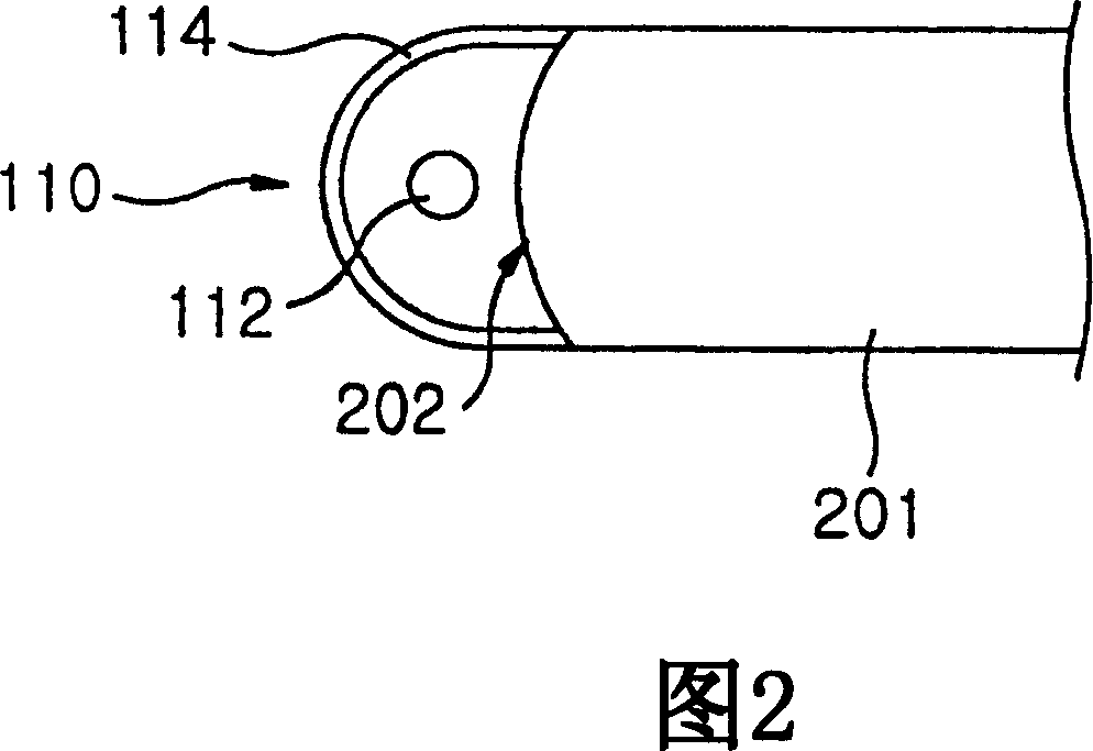
[0036] 2 is a sectional view partially showing a light source and a light guide plate arranged in a BLU according to a first embodiment of the present invention.

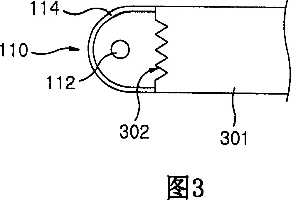
[0037] As described above, the light source 110 includes the light source reflector 114 and the light source 112 mounted on the light source reflector 114 .

[0038] The i...


PUM


Abstract

The present invention relates to a back light unit. Particularly, the present invention relates to a back light unit which can increase the efficiency of light condensation. A back light unit according to the present invention comprises a light source unit; a light guiding plate for changing and emitting the light incident from the light source unit into surface light, and having a means for preventing light loss on an incident surface facing the light source unit; and a prism sheet located on the upper surface of the light guiding plate, each prism facing the light guiding plate. Preferably, the means for preventing light loss is protuberantly formed on the incident surface toward the light source unit, or in the form of prism on the incident surface. And, preferably, the means for preventing light loss is a fresnel lens attached onto the incident surface. Preferably, the means for preventing light loss has an oblique surface which is curved. The back light unit further includes a reflective sheet (130) located on the lower surface of the light guiding plate to reflect the light emitted from the light guiding plate.

Description

technical field [0001] The present invention relates to a backlight unit, and more particularly, the present invention relates to a backlight unit capable of increasing light collection efficiency. Background technique [0002] A liquid crystal display device (hereinafter, "LCD device") is an electrical device that changes electrical data generated from many devices into visible data, and transmits them by using changes in crystal transmittance according to applied voltage. [0003] An LCD device is a device for displaying information, but it does not have a light source itself. Therefore, the LCD device requires an additional device in order to uniformly illuminate the entire screen of the LCD device by the light source installed on the back of the LCD device. As such additional equipment, a backlight unit (hereinafter, referred to as "BLU") that supplies light to the screen of the LCD is used. [0004] The BLU is classified into a direct-illumination type and an edge-ill...

Claims


Application Information

Patent Timeline
IPC IPC(8): G02F1/1335G02B5/04
Inventor 李承浩李相坤
Owner LG ELECTRONICS INC
Learn More