Working impeller of hydraulic coupler

A technology of hydraulic coupling and impeller, applied in belt/chain/gear, fluid transmission, mechanical equipment, etc., can solve the problems of increasing impeller material cost, increasing motor load inertia, increasing impeller weight, etc., to save materials , the effect of reducing load inertia and increasing consumption

Inactive Publication Date: 2007-04-18
大连创思福液力偶合器成套设备有限公司
View PDF0 Cites 4 Cited by
  • Summary
  • Abstract
  • Description
  • Claims
  • Application Information

AI Technical Summary

Problems solved by technology

It solves the problem that the blades of traditional impellers need to design the blade thickness according to the strength requirements at the maximum diameter, avoiding the waste caused by excessive strength design, and avoiding the reduction of the cross-sectional area of ​​the flow due to the increase of the average thickness of the blades, which reduces the hydraulic efficiency. problem; also solved the problems of increased impeller material cost, increased impeller weight, and increased motor load inertia due to the increase in the average thickness of the blades

Method used


Image

  • Working impeller of hydraulic coupler
  • Working impeller of hydraulic coupler

Examples


Embodiment Construction

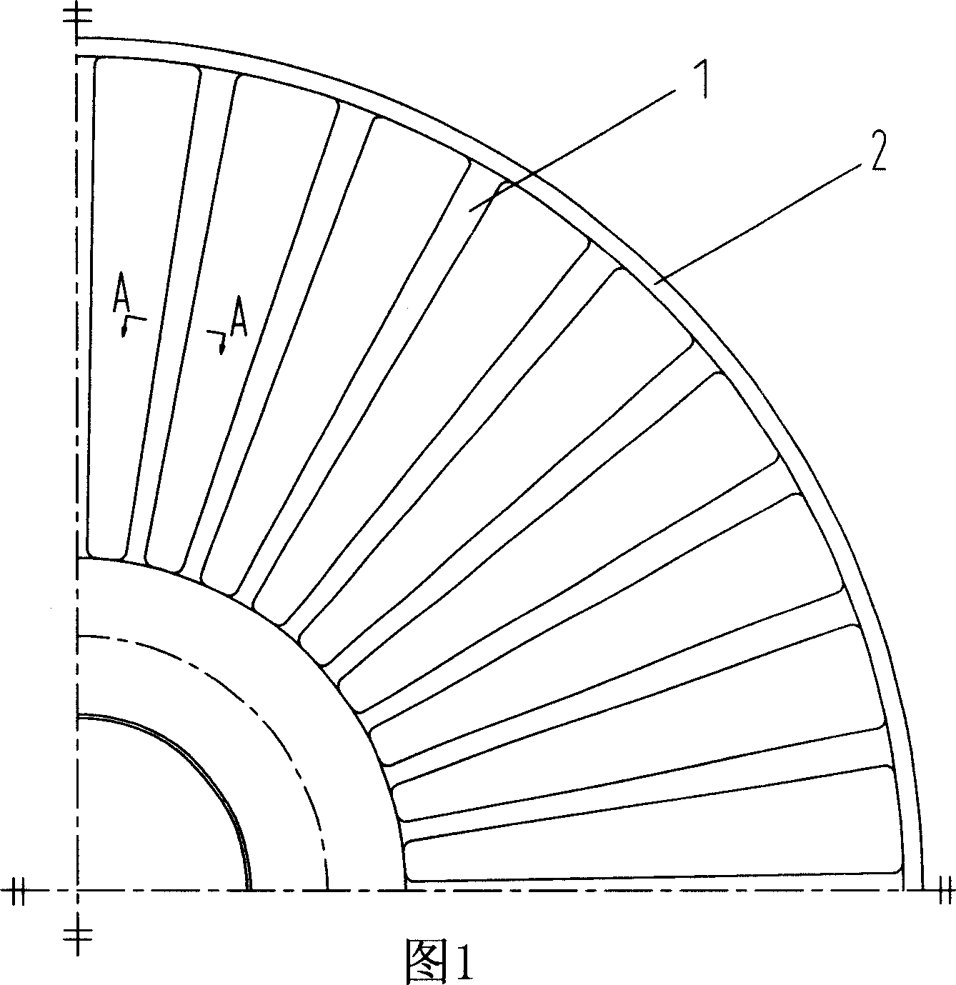
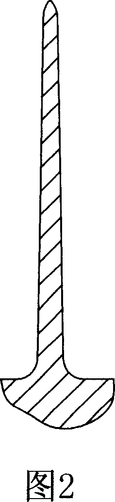
[0008] Fig. 1 is an axial projection view of a cast aluminum alloy impeller according to the present invention. In this embodiment, as shown in Figure 1, the partial structure of the working impeller of the speed-regulating fluid coupling, wherein, the impeller 2 is uniformly distributed with blades 1 in the circumferential direction, and the blades 1 are connected to the cast aluminum alloy impeller body 2 by the root. into one. The key improvement of the present invention is that the blade 1 has a variable cross-section structure both in the radial direction and in the axial direction. Specifically, as shown in Figure 1, the thickness of the blade 1 gradually increases as the diameter increases in the radial direction; referring to the cross-sectional structure along the A-A direction in Figure 1 shown in Figure 2, the blade 1 gradually moves away from the root in the axial direction , the thickness gradually decreases.

[0009] The design of the two-way variable cross-sec...


PUM


Abstract

There is disclosed an operating impeller of a hydraulic coupler, which comprises blades fixed on the impeller main body. The invention adopts the blades of radial and axial variable cross-section, so it can guarantee the strength of the blades in the position of different diameters and in the different axial positions and reduce the weight of the blades and meanwhile reduce the load inertia of the motor.

Description

technical field [0001] The invention relates to a hydraulic coupling, more specifically, relates to the improvement of the structure of the working impeller blade of the hydraulic coupling, which is mainly used for the speed-regulating hydraulic coupling. Background technique [0002] The cast aluminum alloy working impeller of the hydraulic coupling, the vanes of the impeller of the prior art are all arranged with equal thickness on the axial and radial sections. In the actual working process, the stresses on different diameters of the impeller along the radial direction are different. The larger the diameter, the greater the stress and the higher the strength requirements. Similarly, the axial stress of the impeller is also different. The closer to the root of the blade, the greater the stress and the higher the strength requirements. Obviously, the design of equal-thickness blades is difficult to meet the strength requirements. In order to meet the strength requirements...

Claims


Application Information

Patent Timeline
Patent Type & Authority Applications(China)
IPC IPC(8): F16H41/26
Inventor 曹晓宁
Owner 大连创思福液力偶合器成套设备有限公司
Why Eureka
Try Eureka