
In-situ substrate imaging

A substrate and substrate layer technology, which is applied in grinding machine tools, manufacturing tools, and components of grinding machine tools, etc., can solve problems such as unusable substrates

Inactive Publication Date: 2007-04-11
APPLIED MATERIALS INC
View PDF1 Cites 1 Cited by
  • Summary
  • Abstract
  • Description
  • Claims
  • Application Information

AI Technical Summary

Problems solved by technology

Alternatively, inspection may reveal that excess material has been removed, thereby rendering the substrate unusable

Method used


Image

  • In-situ substrate imaging
  • In-situ substrate imaging
  • In-situ substrate imaging

Examples


Embodiment Construction

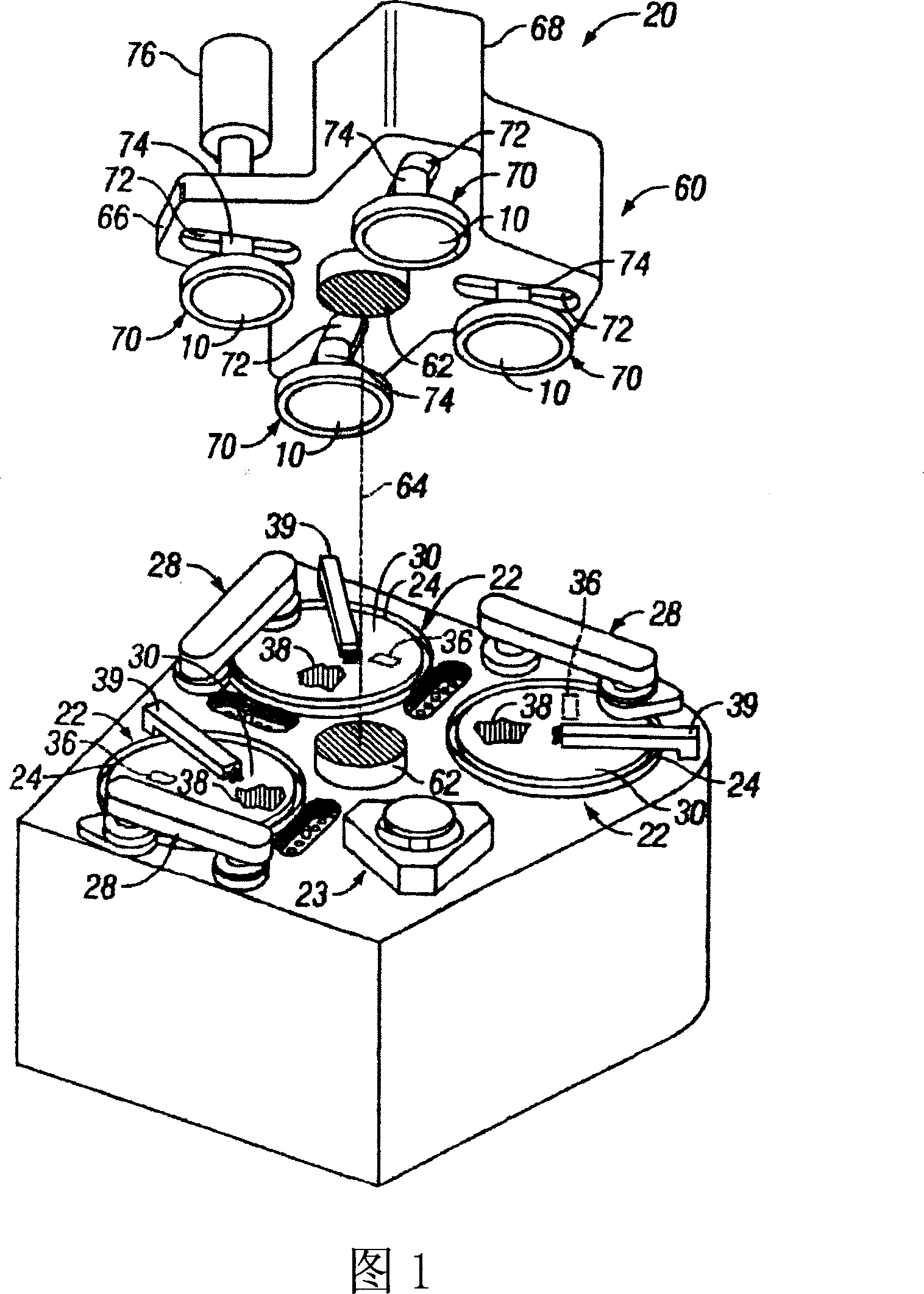
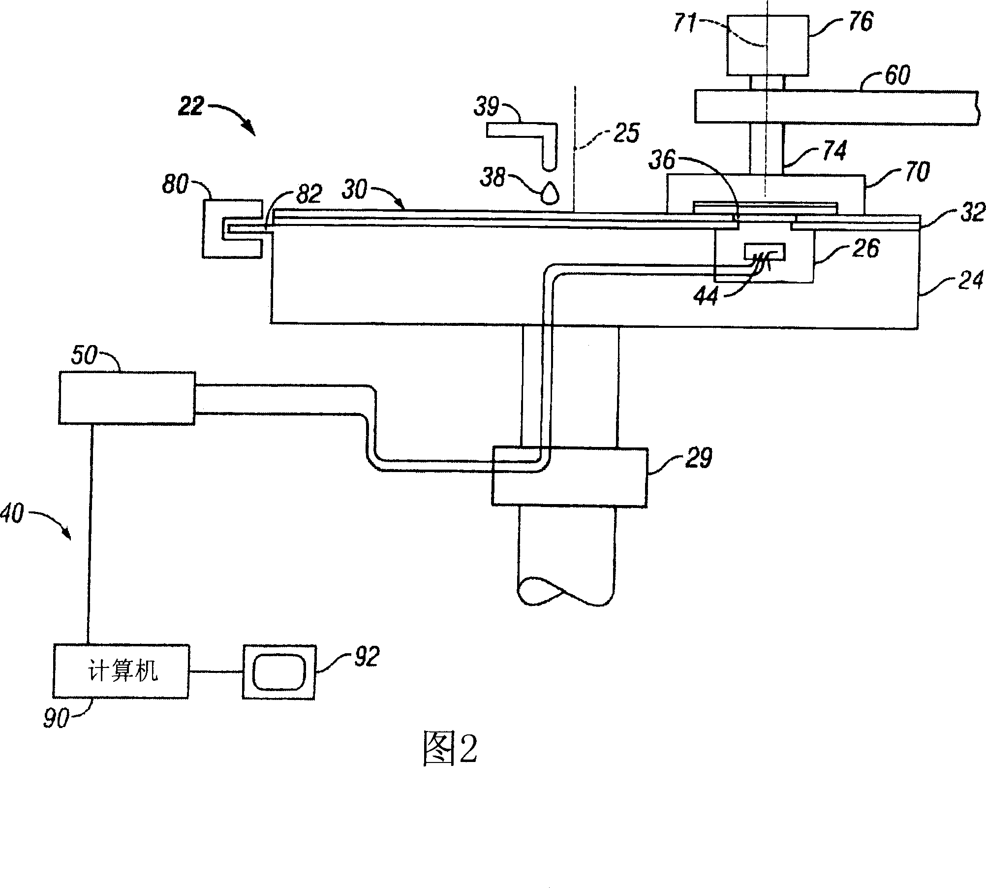
[0021] FIG. 1 shows a chemical mechanical polishing apparatus 20 capable of polishing one or more substrates 10 . The polishing apparatus 20 includes a series of polishing tables 22 and transfer tables 23 . The transfer station 23 transfers the substrate between the carrier head 70 and the loading device.

[0022] Each polishing station includes a rotatable platen 24 on which a polishing pad 30 is disposed. The first and second stations may include a two-layer polishing pad with a harder, durable outer surface or a fixed abrasive pad embedded with abrasive particles. The last polishing station may include a relatively soft pad. Each polishing station may also include a pad conditioning device 28 for maintaining the condition of the polishing pad to effectively polish the substrate.

[0023] A rotatable multi-head carousel 60 supports four carrier heads 70 . By means of a carousel motor assembly (not shown), the carousel is rotated about a carousel shaft 64 via a central co...


PUM


Abstract

Methods and products, including computer program products, for endpoint determination. An image of a portion of a substrate is captured in-situ, where the image includes optical information that depends on a thickness of a substrate layer. The image is examined to find a location on the substrate, and a process endpoint is determined using a portion of the optical information that corresponds to the location.

Description

technical field [0001] The present invention relates to chemical mechanical polishing of substrates. Background technique [0002] Integrated circuits are typically formed on a silicon substrate by sequentially depositing conductive, semiconductive, or insulating layers on a silicon substrate. One fabrication step involves depositing a filler layer on a non-planar surface and planarizing the filler layer until the non-planar surface is exposed. For example, a metal filler layer can be deposited on the patterned oxide layer to fill trenches or holes in the oxide layer. The filler layer is then polished until the raised pattern of the oxide layer is exposed. After planarization, the portion of the metal layer remaining in the trench provides circuitry on the substrate. In addition, the substrate surface to be subjected to photolithography also needs to be planarized. [0003] Chemical mechanical polishing (CMP) is a well-established planarization method. This planarizatio...

Claims


Application Information

Patent Timeline
Patent Type & Authority Applications(China)
IPC IPC(8): B24B49/12B24B29/02H01L21/304
CPCB24B49/12H01L21/67253B24B37/013
Inventor 杰弗里·德鲁·戴维尼尔斯·约翰逊博古斯拉夫·A·斯韦德克
Owner APPLIED MATERIALS INC
Learn More