
Bone anchoring element

A component and anchoring technology, which is applied in the field of bone anchoring components, can solve problems such as inability to achieve insertion, achieve fast and firm anchoring, and be easy to manufacture

Active Publication Date: 2007-04-11
BIEDERMANN TECH GMBH & CO KG
View PDF4 Cites 12 Cited by
  • Summary
  • Abstract
  • Description
  • Claims
  • Application Information

AI Technical Summary

Problems solved by technology

In addition, the wedge-like shape of the retaining element itself does not allow easy insertion

Method used


Image

  • Bone anchoring element
  • Bone anchoring element
  • Bone anchoring element

Examples


Embodiment Construction

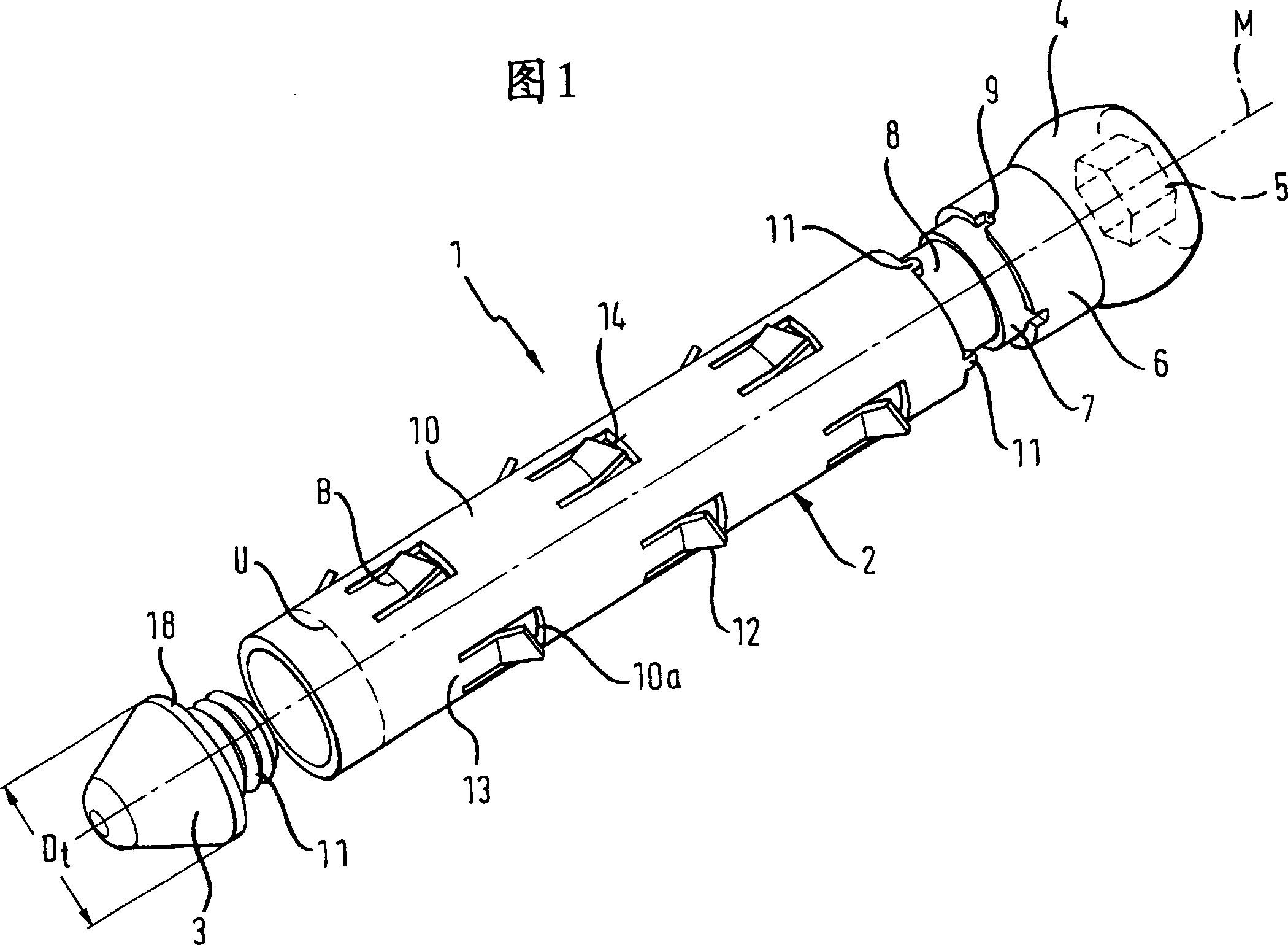
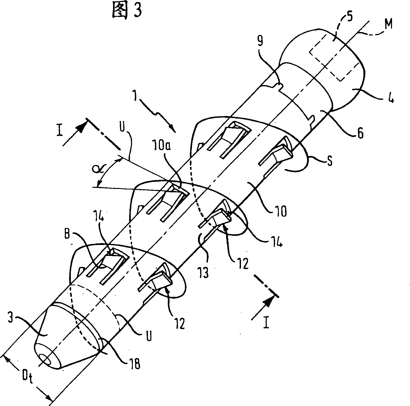
[0026] A bone anchoring member according to a first embodiment of the present invention is explained with reference to FIGS. 1 to 5 . The bone anchoring element 1 comprises a shaft 2 having a tip 3 at one end and a head 4 at the other end. The head 4 is in the shape of a truncated ball and has at its free end a groove 5 for engagement with a screw tool. A first cylindrical portion 6 adjoins the head 4 . The outer diameter of the first cylindrical portion 6 is slightly smaller than the diameter of the head 4 . Adjacent to the first cylindrical portion and on the side opposite to the head 4, a second cylindrical portion 7 is provided. The diameter of the second cylindrical portion 7 is smaller than that of the first cylindrical portion 6, thereby forming a step. Adjacent to the second cylindrical portion 7 a cylindrical rod 8 is arranged. The diameter of the cylindrical rod 8 is smaller than the diameter of the second cylindrical part 7 .

[0027] On the edge of the first c...


PUM


Abstract

A bone anchoring element (1; 101; 201; 301) provided with a rod for anchoring in a bone (20; 325; 340). At least one barb element (12; 112) is attached to the rod (2; 202; 302), the barb element (12; 112) having a free end (14; 114) and a barb element (12; 112) Seat edge (13) connected to said rod (2; 202; 302). The barb element has a first portion (15) adjacent to the seat edge (13) and a second portion (16; 116) adjacent to the free end (14; 114). The second part is inclined relative to the first part in a direction away from said rod (2; 202; 302).

Description

technical field [0001] The invention relates to a bone anchoring element comprising a plurality of barb elements attached to its shaft and to a method of producing the bone anchoring element. Background technique [0002] EP0714643A1 discloses a bone fixation device such as a screw, pin, staple, wire or anchor having a micro-textured contact surface to enhance the mounting or clamping performance of the device. The microstructured contact surface contains oriented asymmetric or angled hanging features (such as diagonal teeth) that snap or flex to limit motion in one direction, yet flex or slide to allow relatively easy movement in the other direction. Contact moves. [0003] DE19801219A1 discloses a bone screw with rigid barb-like protrusions arranged in a plurality of circumferential rows around the bone screw. The barbed protrusion has a serrated shape, which not only facilitates the insertion of the bone screw but also prevents the bone screw from loosening. However, i...

Claims


Application Information

Patent Timeline
IPC IPC(8): A61B17/56
CPCA61B17/866A61B17/8685A61B2017/8655A61B17/68A61B17/863A61B2017/00867A61B17/864A61B17/7266A61B17/56A61B17/58
Inventor W·马蒂斯L·比德尔曼
Owner BIEDERMANN TECH GMBH & CO KG
Learn More