
Traffic vehicle speed monitoring system

A vehicle and speed measurement technology, applied in traffic flow detection, control devices, ceramic molding machines, etc., can solve the problems of high work intensity, expensive equipment, and difficulty of police officers on duty, and achieve satisfactory engineering accuracy, reliability, and effectiveness. Monitor vehicle speed and create simple effects

Inactive Publication Date: 2007-03-28
SHANTOU UNIV
View PDF0 Cites 8 Cited by
  • Summary
  • Abstract
  • Description
  • Claims
  • Application Information

AI Technical Summary

Problems solved by technology

In view of the principle of laser speed measurement, the laser beam must be aimed at the plane reflection point perpendicular to the laser beam, and because the measured vehicle is too far away and in a moving state, or the plane of the vehicle body is not large, the success rate of laser speed measurement is low and difficult. Large, especially the work of the police officers on duty is very intensive and they are prone to fatigue
and expensive equipment

Method used


Image

  • Traffic vehicle speed monitoring system
  • Traffic vehicle speed monitoring system
  • Traffic vehicle speed monitoring system

Examples


Embodiment 1

[0055] The other parts of the vehicle speed measurement system of the present invention are as described above, and the method of calculating the speed and judging whether the vehicle is the same vehicle or not is described in this embodiment according to the detected signals. The process of speed calculation and whether it is the same vehicle includes steps as shown in Figure 13:

[0056] 1. There is an N-axis vehicle passing through the concrete member on the road surface, and the system detects the corresponding pulse signal, among which,

[0057] The pulse signals obtained from component 1 are shown in Figure 12a, and the time points are T11, T12, ... T1n,

[0058] The pulse signals obtained from component 2 are shown in Fig. 12b, and the time points are respectively T21, T22, ... T2n.

[0059] 2. It can be seen that the time when the first shaft passes through member 1 and member 2 is T11 and T21 respectively, then the vehicle speed can be obtained as: V=S / (T21-T11).

...


PUM

PropertyMeasurementUnit
particle diameteraaaaaaaaaa

Abstract

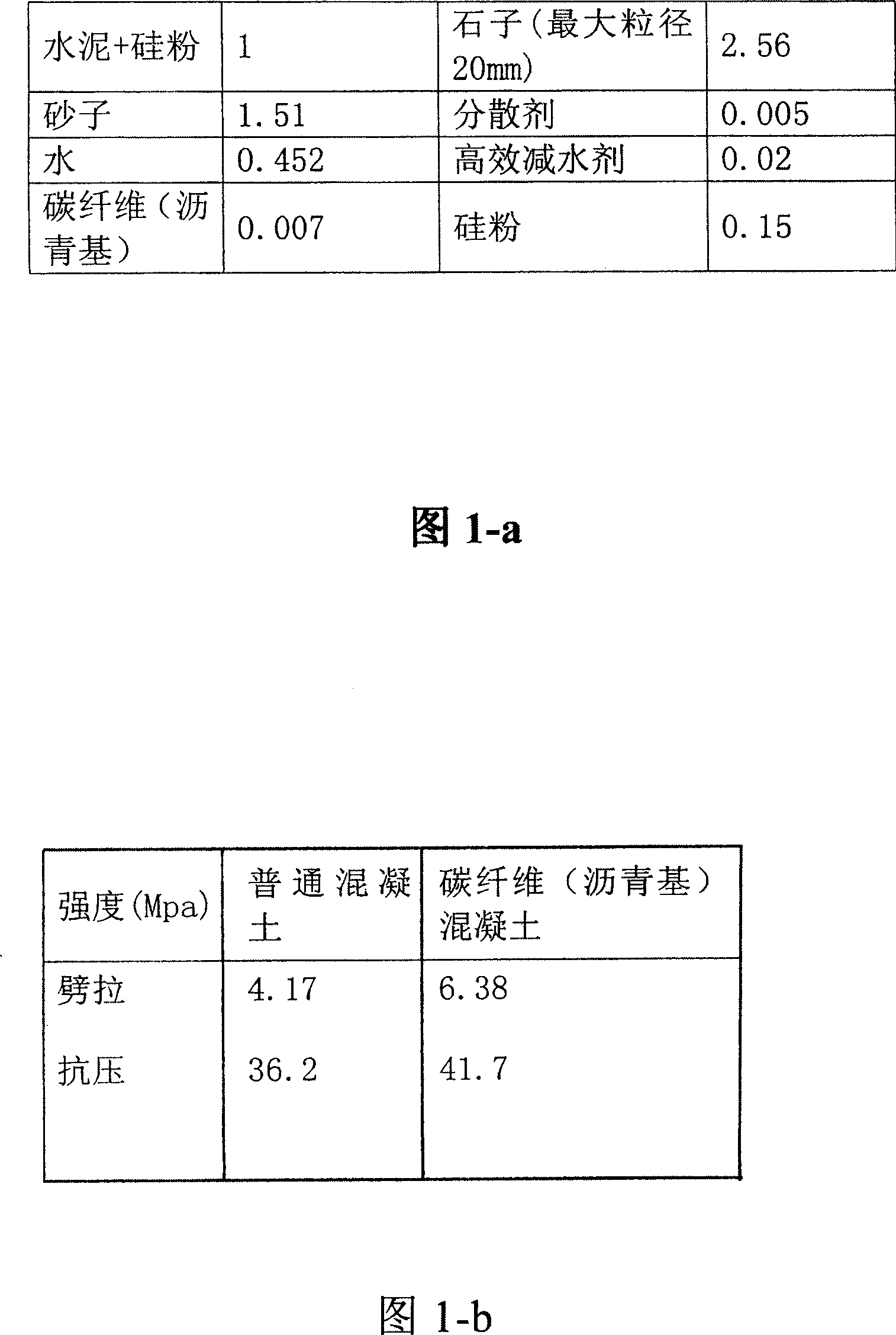
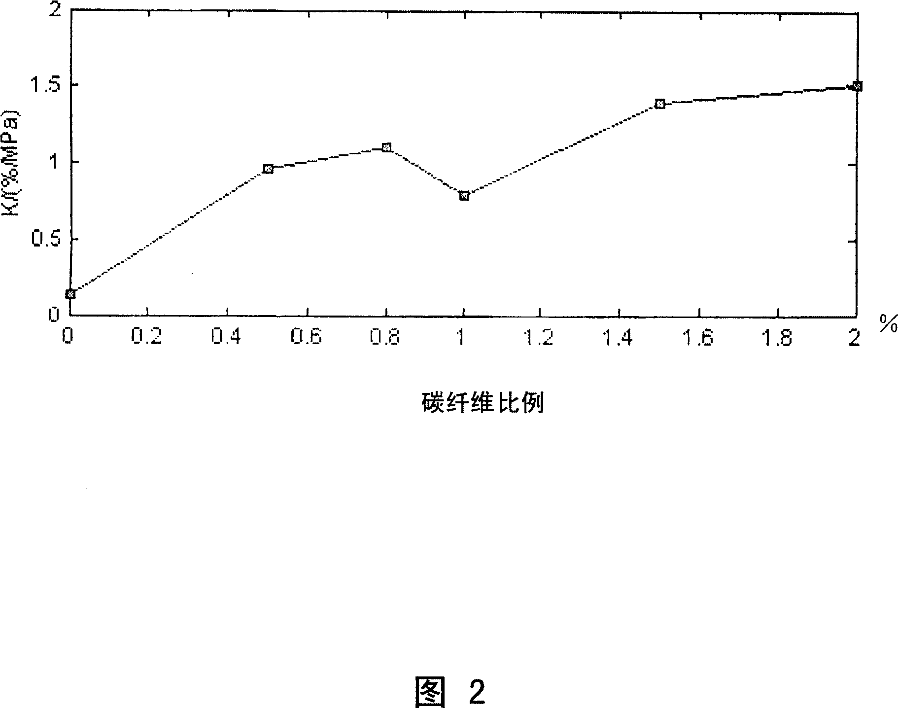
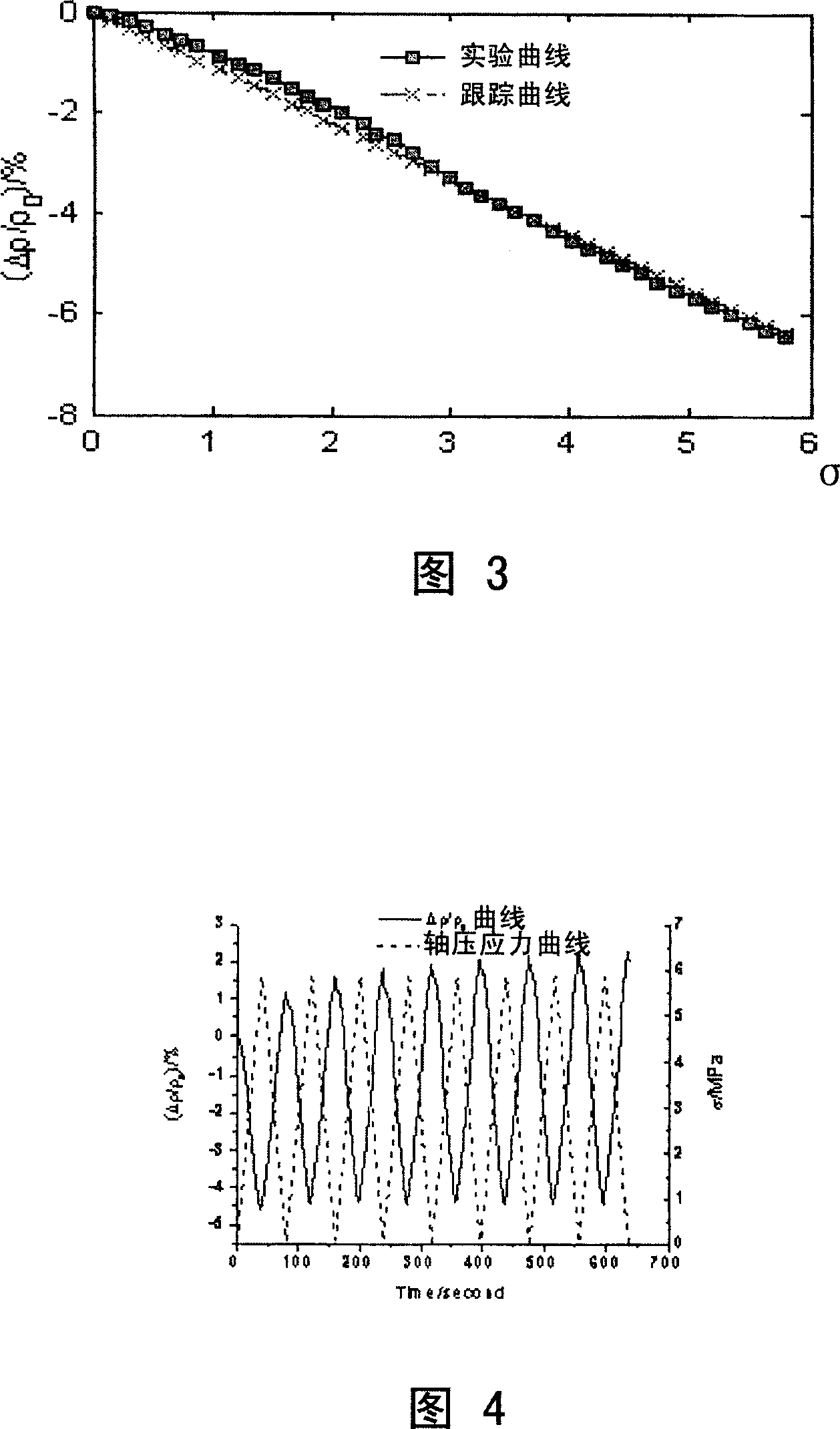
The invention discloses a carbon fiber concrete material and the making process thereof, and a road vehicle speed monitoring system based on its pressure-sensitive property. And the system comprises two concrete components made of it, parallelly arranged on the road surface about 10-15 meters distant from the vehicle, where the top and bottom sides are euipped with special electrodes; and singal collecting system, used to collect resistance variation signals generated by pressing of the components; and singal analyzing and judging system, used to analyze and judge the collected signals and calculate vehicle speed and send out alarm singal to an alarm device when the vehicle speed exceeds the preset limited value. Besides, it can count road vehicle flow. And the system can effectively monitor vehicle speeds, able to operate day and night and widely applied.

Description

technical field [0001] The invention relates to a road traffic monitoring system, in particular to a system for monitoring the speed of traffic vehicles by using the traffic vehicles' induction of road surface pressure. Background technique [0002] In the prior art, radar speed measurement or laser speed measurement is mainly used for vehicle speed measurement. For radar speed measurement, commonly known as electronic eye, the movement speed of the measured object is obtained based on the calculation of the frequency shift of the received reflected wave. Corresponding to the principle of radar speed measurement, anti-speed radar equipment has appeared, which can detect whether there is a radar speed meter around within a certain distance. When the car is running, when the car is close to the radar speedometer, it will make a sound as a reminder, and the driver can reduce the speed of the car. The emergence of anti-speed radar equipment has greatly reduced the actual effec...

Claims


Application Information

Patent Timeline
Patent Type & Authority Applications(China)
IPC IPC(8): C04B28/00C04B14/38C04B24/38C04B14/06B28B1/52B28C7/02G08G1/01
Inventor 谢慧才
Owner SHANTOU UNIV
Learn More