
Separating method for carrier frequency electronic speckle displacement field

A technology of electronic speckle and separation method, applied in the direction of measuring devices, instruments, using optical devices, etc.

Inactive Publication Date: 2007-03-21
SHANDONG NORMAL UNIV
View PDF0 Cites 11 Cited by
  • Summary
  • Abstract
  • Description
  • Claims
  • Application Information

AI Technical Summary

Problems solved by technology

The application of carrier frequency electron speckle method to measure two-dimensional displacement components has not been reported yet

Method used


Image

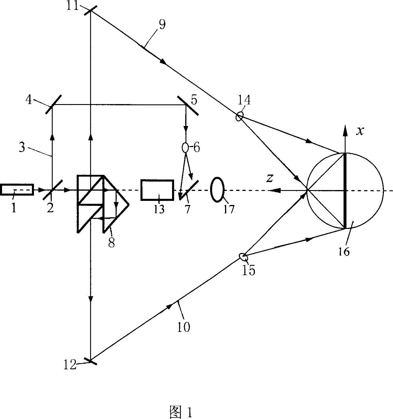
  • Separating method for carrier frequency electronic speckle displacement field
  • Separating method for carrier frequency electronic speckle displacement field
  • Separating method for carrier frequency electronic speckle displacement field

Examples


Embodiment

[0020] In the double-beam type electronic speckle interference light path, a reference light path is added, and the two beams of illumination light share this path of reference light. In this way, a double-beam electronic speckle interference system with the same reference optical path is formed.

[0021] In the optical path system shown in Figure 1, the laser beam emitted by the laser 1 is split by a variable beam splitter, and the beam C 3 is irradiated to the half-transparent mirror 7 after passing through the mirror C 4 , the mirror D 5 and the beam expander C 6 Above, the reference light path is formed by reflection. The transmission part is divided into beam A9 and beam B10 of equal intensity by the combined beam splitter mirror, which are respectively reflected by mirror A11 and mirror B12 and beam expander A14 and beam expander B15, and then irradiated to the measured On the object, a double-beam electronic speckle interference system is formed. The object to be meas...


PUM


Abstract

The invention provides the separation method of the carrier electronic speckle displacement field. The method is: it adds the reference path in the electronic speckle two-beam interference path to make the reference path share by the two beams; it imports the carrier modulation stripe by the deflection object, so the carrier stripe distorts adjusted by the object distortion. The two beams measure the distorting object independently to collect the stripe after the object distortion and get the two frame phase bitmap including the off-face displacement and the in-face displacement component information to separate the in-face displacement field and the off-face displacement field by computing the phase location. The invention can get the high precision measurement result, so it can provide a new way for measuring the deformation field component.

Description

technical field [0001] The invention relates to a separation method of frequency carrier electron speckle displacement field. Background technique [0002] In optomechanical measurement, time phase shift and carrier frequency modulation are two effective phase quantitative measurement techniques. Compared with phase-shift technology, the method of spatial modulation of interference fringes does not require sophisticated phase-shift equipment, has low requirements on the measurement environment, and has the advantage of being suitable for dynamic measurement, which is of great value in practical applications. Since optical interferometry is based on interference fringes to measure the displacement field, the quality of the interference fringes has a great influence on the measurement results. In particular, the spatial modulation of interference fringes requires high-contrast fringes. This method is widely used in holography and moiré interference. The method of spatial mod...

Claims


Application Information

Patent Timeline
IPC IPC(8): G01B11/00G01B11/02G01B11/16
Inventor 孙平
Owner SHANDONG NORMAL UNIV
Learn More