Pump gear

A transmission device, pump head technology, applied in the direction of pumps, components of pumping devices for elastic fluids, multi-cylinder pumps, etc., can solve the limitation of proximity, the high cost of laying pipelines, and the difficulty of satisfying pump location requirements And other issues

Inactive Publication Date: 2007-03-21
BRAN & LUEBBE GMBH
View PDF0 Cites 8 Cited by
  • Summary
  • Abstract
  • Description
  • Claims
  • Application Information

AI Technical Summary

Problems solved by technology

However, the star configuration of the cylinders leads to significant drawbacks
On the one hand, due to the above-mentioned structure, the entire pump protrudes outwards, and the location requirements of the pump are always difficult to meet a satisfactory level; The access to the side cylinders is significantly restricted
In addition, the laying of pipelines requires particularly expensive

Method used


Image

  • Pump gear
  • Pump gear
  • Pump gear

Examples


Embodiment Construction

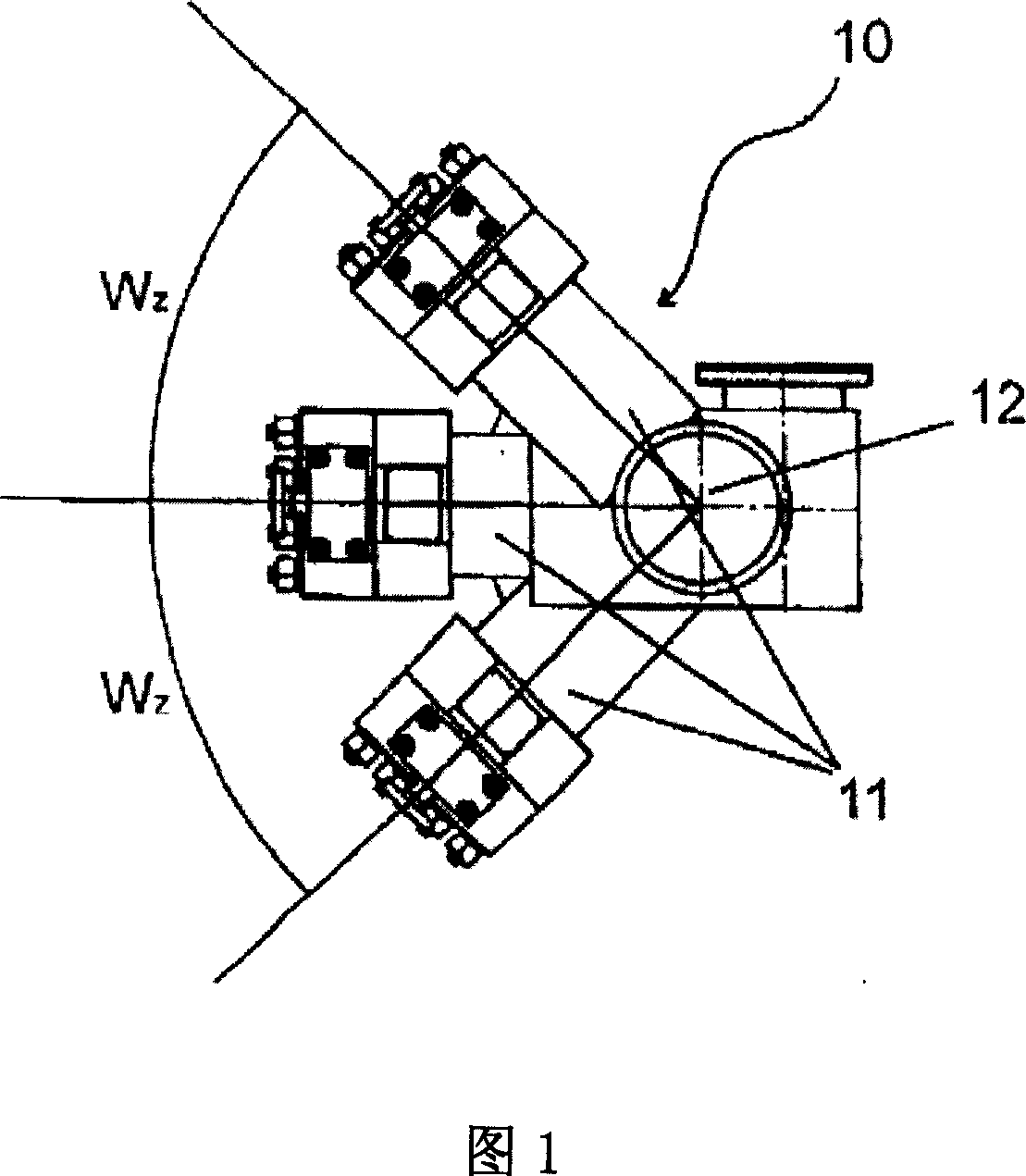
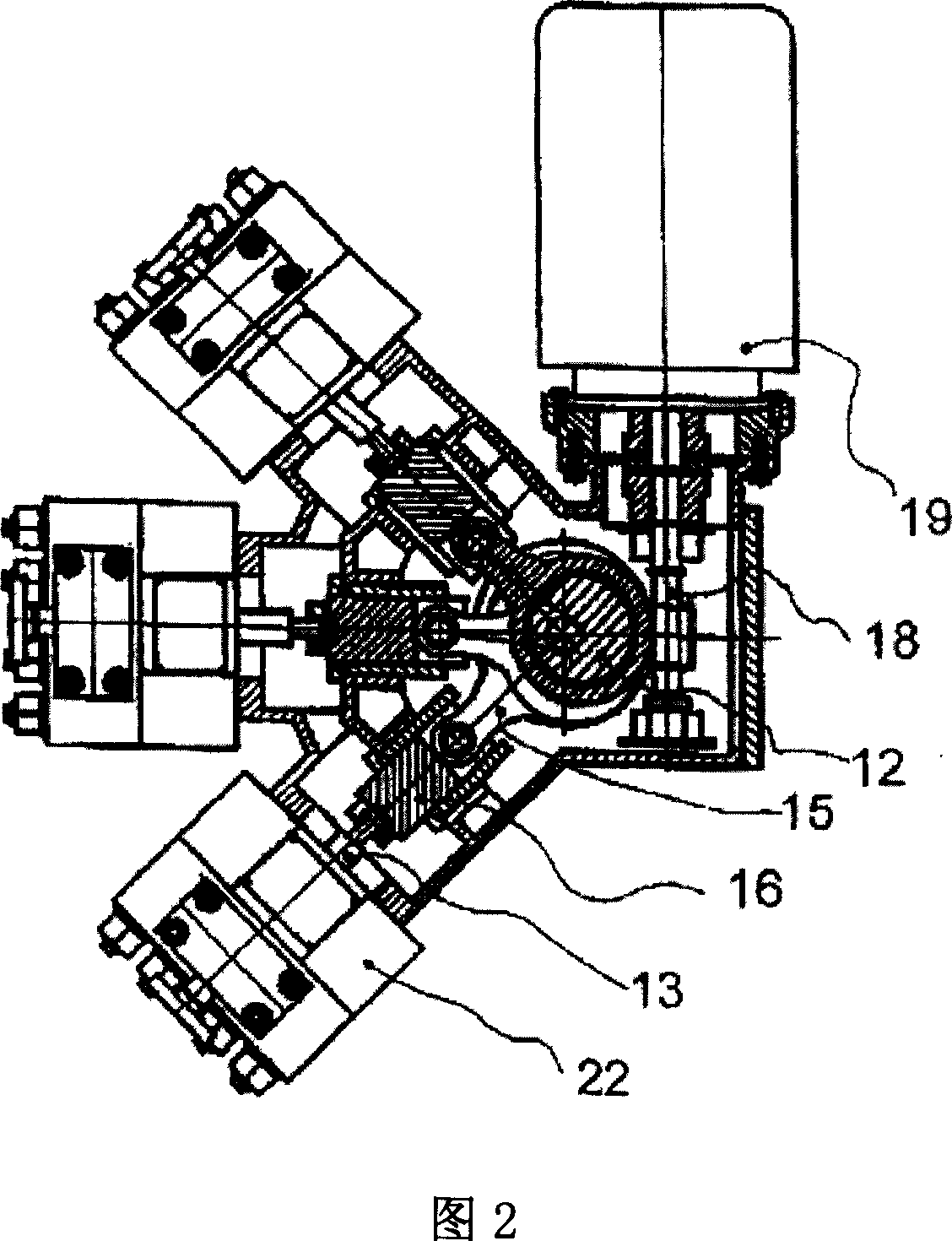
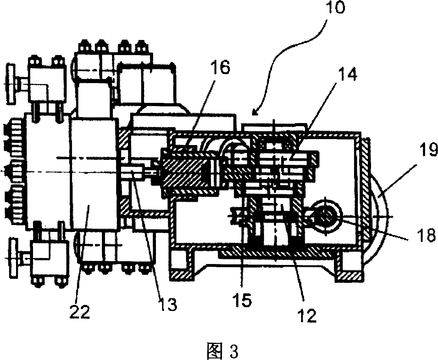
[0037] FIG. 1 shows a possible geometric arrangement of a pump drive 10 according to the invention with three cylinders 11 , viewed from above. The cylinders 11 are shown horizontally radially away from the vertically oriented crankshaft 12 . In this embodiment, the cylinders 11 are arranged symmetrically and each include a rotation angle W relative to one another in projection on a plane perpendicular to the crankshaft 12 z . A pump drive 10 with the same geometrical profile is depicted in more detail in FIG. 2 . The sectional plane of the drawing extends through the uppermost connecting rod 15 . In contrast, the two further connecting rods 15 are supported on the crankshaft 12 directly below the uppermost connecting rod 15 without spacing therebetween. The vertically arranged crankshaft 12 is driven by a drive motor 19 via a horizontally arranged worm gear 18 . On the crankshaft 12, three connecting rods 15 are supported on the respective crank 14, respectively. At thei...


PUM


Abstract

A pump mechanism having multiple cylinders, whose axes are situated around a crankshaft to enclose predetermined angles, and whose pistons are each functionally connected to a connecting rod mounted on a crank on the crankshaft, each connecting rod being mounted on its own crank and the cranks having a predetermined angular offset to one another. This angular offset of the cranks is selected in accordance with the angle which the cylinder axes enclose in such a way that the phase shifts between each two pistons of the cylinders actuated in sequence during a rotation of the crankshaft are equally large.

Description

technical field [0001] The invention relates to a pump drive with a plurality of working cylinders, the axes of which are arranged around a crankshaft in a predetermined angle of rotation, and the pistons of which are each operatively connected to a connecting rod supported on the crank of the crankshaft. Background technique [0002] Multi-cylinder pump drives are used in process pumps for delivering large delivery volumes or in high pressure situations. Among them, as the pump head, most consider the application of the diaphragm pump head. Since the membranes used therein have only a limited deflection capability, membrane pump heads with large diameters are necessary for large delivery volumes. Thus, when very large diaphragm pump heads are used and driven with a multi-cylinder pump drive, the spacing between the pump head positioners or the spacing between the cylinders must be sufficiently large. In conventional pump drives, the individual cylinders are generally arra...

Claims


Application Information

Patent Timeline
Patent Type & Authority Applications(China)
IPC IPC(8): F04B1/16
CPCF04B1/0421F04B1/0413F04B53/006F04B1/0404F04B1/0408
Inventor 迪尔克·彼得森
Owner BRAN & LUEBBE GMBH
Why Eureka
Try Eureka