Non-leaking water-saving cistern according to requirement water
A technology of water tank and outer water tank, which is applied in the field of water tanks of sanitary ware, and can solve the problems of water-saving water tanks with casing structures that have not been seen yet.
- Summary
- Abstract
- Description
- Claims
- Application Information
AI Technical Summary
Problems solved by technology
Method used
Image

Examples
Embodiment 1
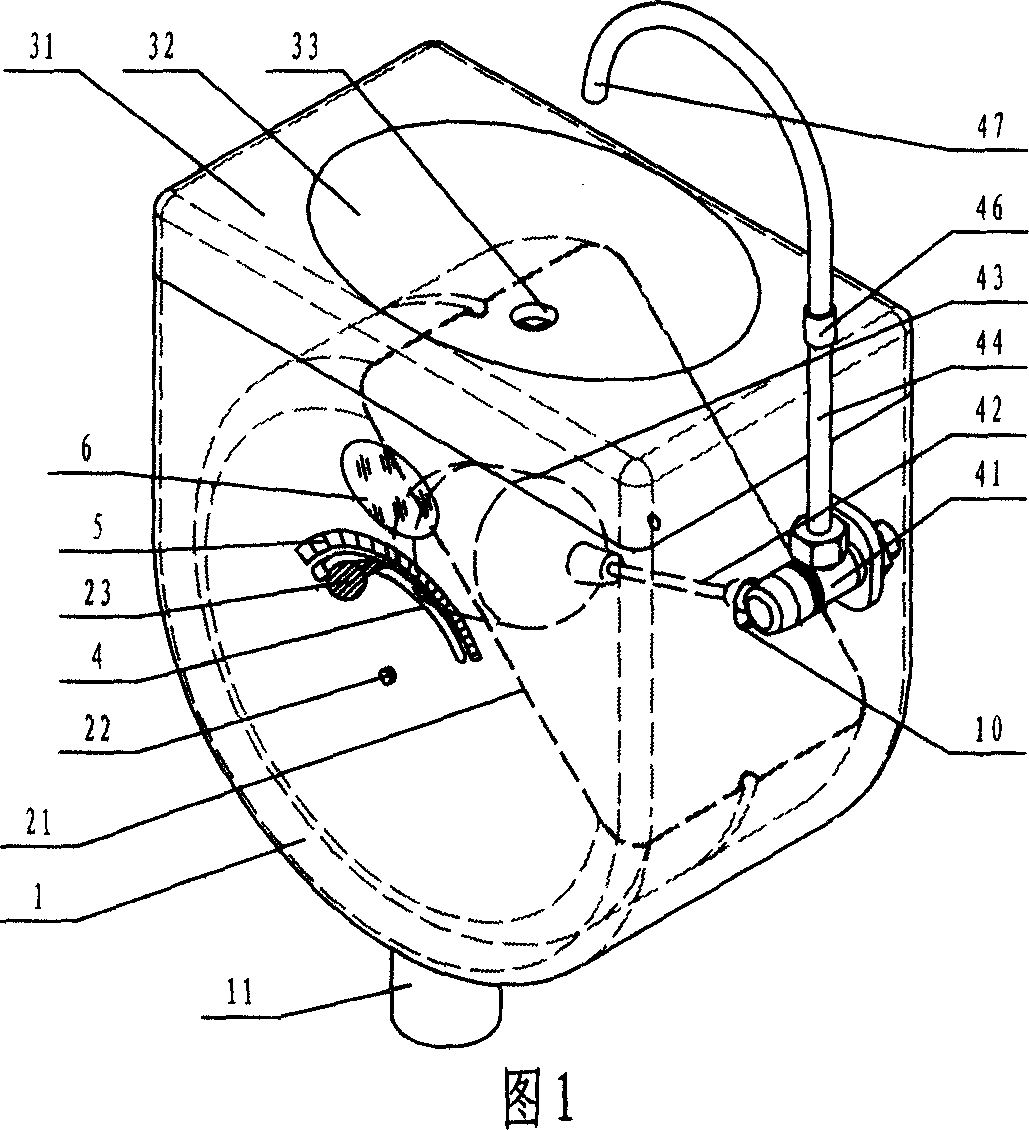
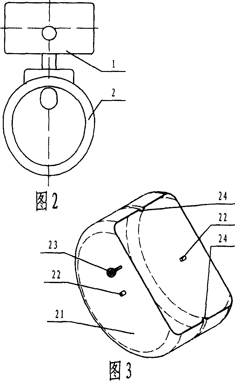
[0077] Please refer to Fig. 1, there is a rectangle and the lower half is the outer water tank 1 of circular arc, and the top of outer water tank 1 is provided with water tank cover 31, and water tank cover 31 is made the parts with water basin 32; An inner water tank 21 is installed in the middle, and on the axis of rotation, two concentric shafts 22 passing between the outer water tank 1 and the inner water tank 21 are supported and connected in a transition fit manner. Have the lever hole 11 that cooperates water inlet valve 41 on the outer water tank 1; 43 is integrated with the switch handle of the water inlet valve, and the floating body 43 falls into the inner water tank 21; the outlet of the water inlet valve 41 is connected with a connecting pipe 44 stretching to the top of the outer water tank 1; the inner water tank 21 is equipped with an operating handle 23 , the handle 23 passes through the arc groove 5 on the outer water tank 1 and is fixed on the inner water tan...
Embodiment 2
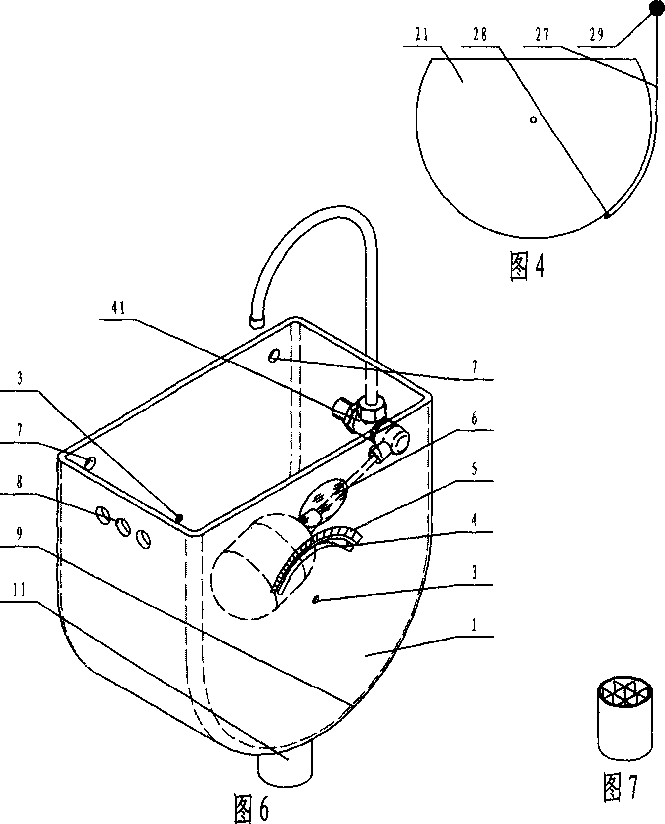
[0079] Figure 10 shows a water-saving water tank that can also be used as a secondary water source, and is suitable for water-deficient places. The main difference with the aforementioned is that the secondary water source can be directly injected into the inner water tank 21 because it does not have a water tank cover. Water inlet valve 41 is fixed in the case, and the water inlet interface 45 of its pipe thread is outside the case. When the secondary water source is in short supply, the valve can be switched to provide water supply from tap water instead.
Embodiment 3
[0081] Fig. 11 shows a water-saving elevated water tank of a squatting toilet. No need for a water tank cover, for the convenience of detecting accidental upper leakage, the water outlet of the water inlet valve 41 is designed above the water tank, and the end of the upper water outlet elbow 47 is exactly the water outlet; Directly fixed on a concentric shaft 22 of the inner water tank 21; the scale mark 5 is located at the lower half of the outer water tank 1.
PUM
 Abstract
Description
Claims
Application Information
 - Generate Ideas
- Intellectual Property
- Life Sciences
- Materials
- Tech Scout
- Unparalleled Data Quality
- Higher Quality Content
- 60% Fewer Hallucinations
Browse by: Latest US Patents, China's latest patents, Technical Efficacy Thesaurus, Application Domain, Technology Topic, Popular Technical Reports.
© 2025 PatSnap. All rights reserved.Legal|Privacy policy|Modern Slavery Act Transparency Statement|Sitemap|About US| Contact US: help@patsnap.com