
Multi-output current-resonant type DC-DC converter

A current resonance, DC-DC technology, applied in the direction of conversion equipment with intermediate conversion to AC, can solve the problem of output voltage fluctuation of the second rectification and smoothing circuit, and achieve the effect of less power conversion loss and high power conversion efficiency.

Inactive Publication Date: 2007-03-07
SANKEN ELECTRIC CO LTD
View PDF2 Cites 24 Cited by
  • Summary
  • Abstract
  • Description
  • Claims
  • Application Information

AI Technical Summary

Problems solved by technology

However, in fact, the transformer (5) does not constitute an ideal electromagnetic coupling. In addition, the second The output voltage of the rectification smoothing circuit (17) changes

Method used


Image

  • Multi-output current-resonant type DC-DC converter
  • Multi-output current-resonant type DC-DC converter
  • Multi-output current-resonant type DC-DC converter

Examples


Embodiment Construction

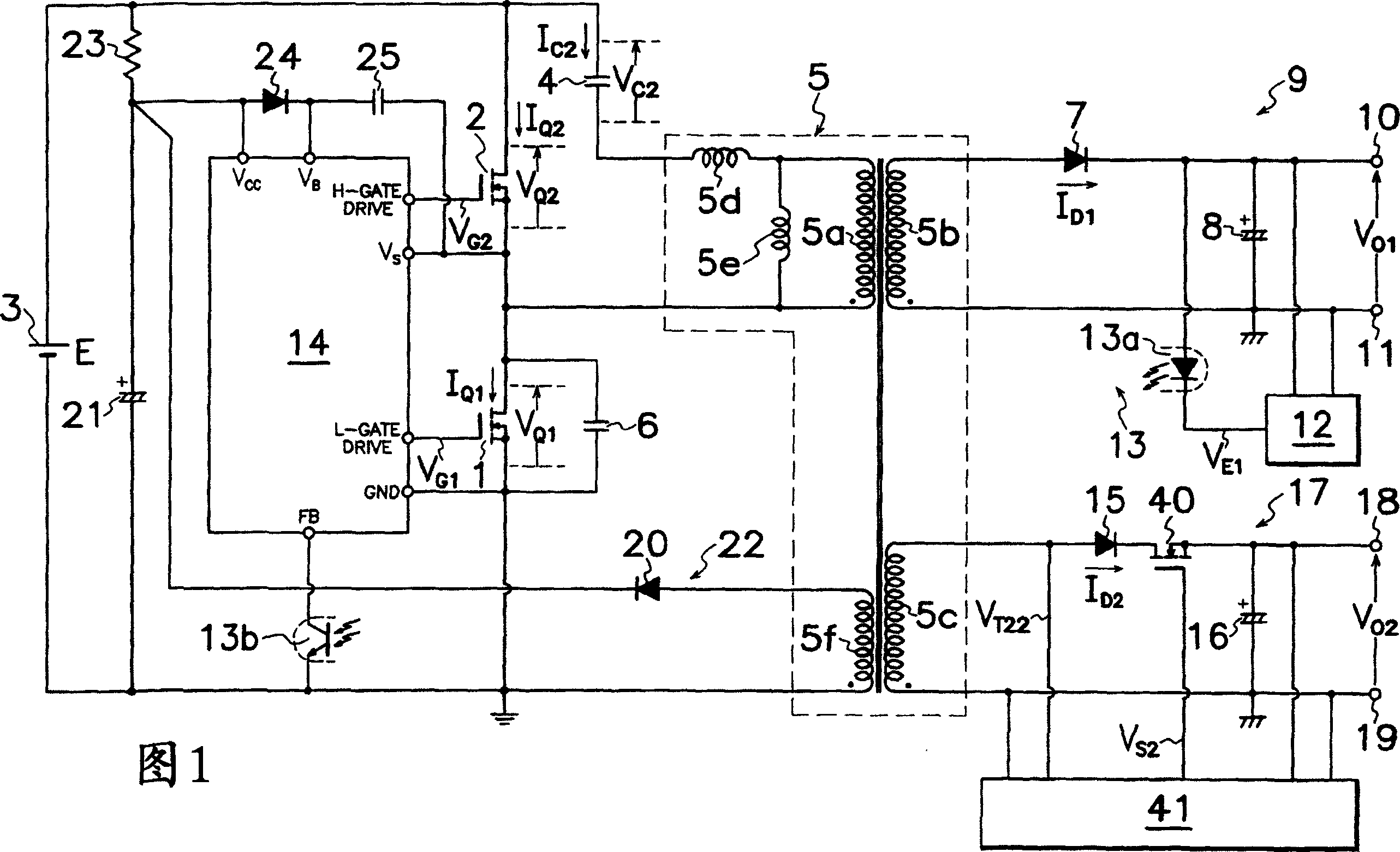
[0174] Hereinafter, first to seventeenth embodiments of the multi-output current resonance type DC-DC converter of the present invention will be described based on FIGS. 1 to 34 . In FIGS. 1 to 34 , the same numerals are assigned to the parts substantially at the same positions as those shown in FIG. 35 , and description thereof will be omitted.

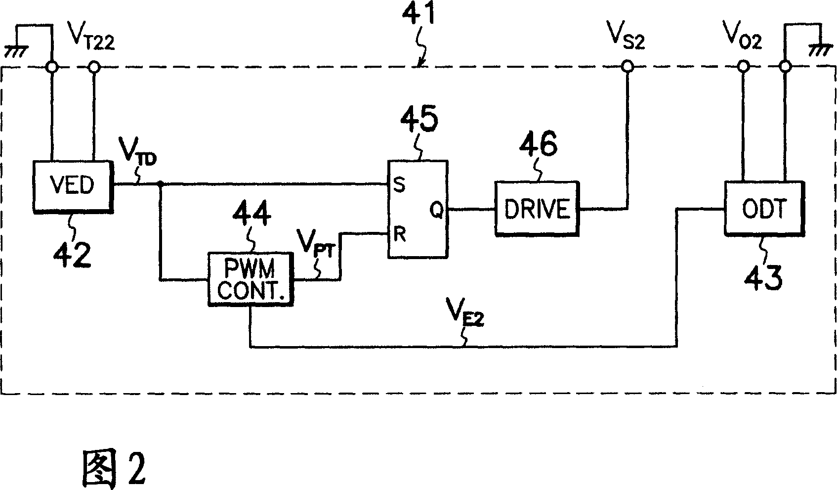
[0175] The multi-output current resonance type DC-DC converter shown in FIG. 1 that represents the first embodiment of the present invention omits the step-down chopper circuit (30) and the chopper control circuit (31) shown in FIG. 2 Between the cathode of the second output rectifying diode (15) of the rectification smoothing circuit (17) and the second output smoothing capacitor (16), connect the output control MOS-FET (40) as the switching element for output control. 2 Between the DC output terminals (18, 19) and the gate of the MOS-FET (40) for output control, a voltage V according to the second auxiliary smoothing capacitor (16)...


PUM


Abstract

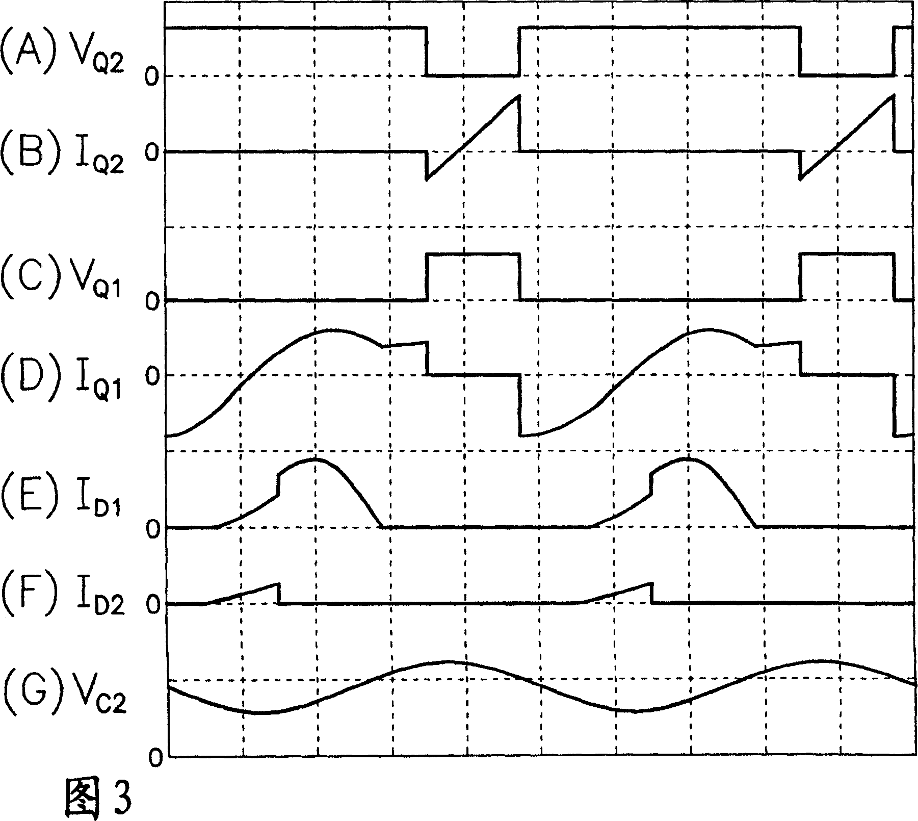
A multi-output current-resonant type DC-DC converter comprises an output controlling MOS-FET (40) connected between a second secondary winding (5c) of a transformer (5) and a second output smoothing capacitor (16) of a second rectification smoothing circuit (17), and an output control circuit (41) for controlling the ON / OFF of an output controlling MOS-FET (40) on the basis of the voltage V02 of the second output smoothing capacitor (16). By turning ON / OFF the output controlling MOS-FET (40) in synchronism with the switching frequency of a first or second main MOS-FET (1, 2), it is made possible to achieve an ideal cross regulation with each DC output and to achieve a highly stable DC output with a little power conversion loss and with a simple circuit change. The multi-output current-resonant type DC-DC converter realized is inexpensive but high in the power conversion efficiency, and can have a highly precise DC output.

Description

technical field [0001] The present invention relates to a multi-output current resonance type DC-DC converter that generates a plurality of direct current outputs, and in particular to a current resonance type DC converter that improves the overall power conversion efficiency by reducing the switching loss in the switching element for output control on the secondary side. - DC converter. Background technique [0002] Through the on-off action of the switching element, the DC input from the DC power supply is converted into high-frequency power and input to the primary winding of the transformer, and then converted into DC power again by the rectifying and smoothing circuits respectively connected to the multiple secondary windings of the transformer, from each A multi-output type DC-DC converter that obtains multiple DC outputs from a rectification smoothing circuit is currently widely used in information equipment such as personal computers, or home appliances such as air c...

Claims


Application Information

Patent Timeline
IPC IPC(8): H02M3/28
Inventor 臼井浩神永行弘大坂升平
Owner SANKEN ELECTRIC CO LTD
Learn More