Conveying unit

A technology of conveying unit and swirl flow, which is applied in the field of conveying unit to achieve the effect of less material consumption and simple pipeline structure

Inactive Publication Date: 2007-03-07
CONTINENTAL AUTOMOTIVE GMBH
View PDF0 Cites 0 Cited by
  • Summary
  • Abstract
  • Description
  • Claims
  • Application Information

AI Technical Summary

Problems solved by technology

Since today's fuel tanks are designed more and more flat, a lot of problems arise when this type of delivery unit is integrated in the fuel tank

Method used


Image

  • Conveying unit
  • Conveying unit
  • Conveying unit

Examples


Embodiment Construction

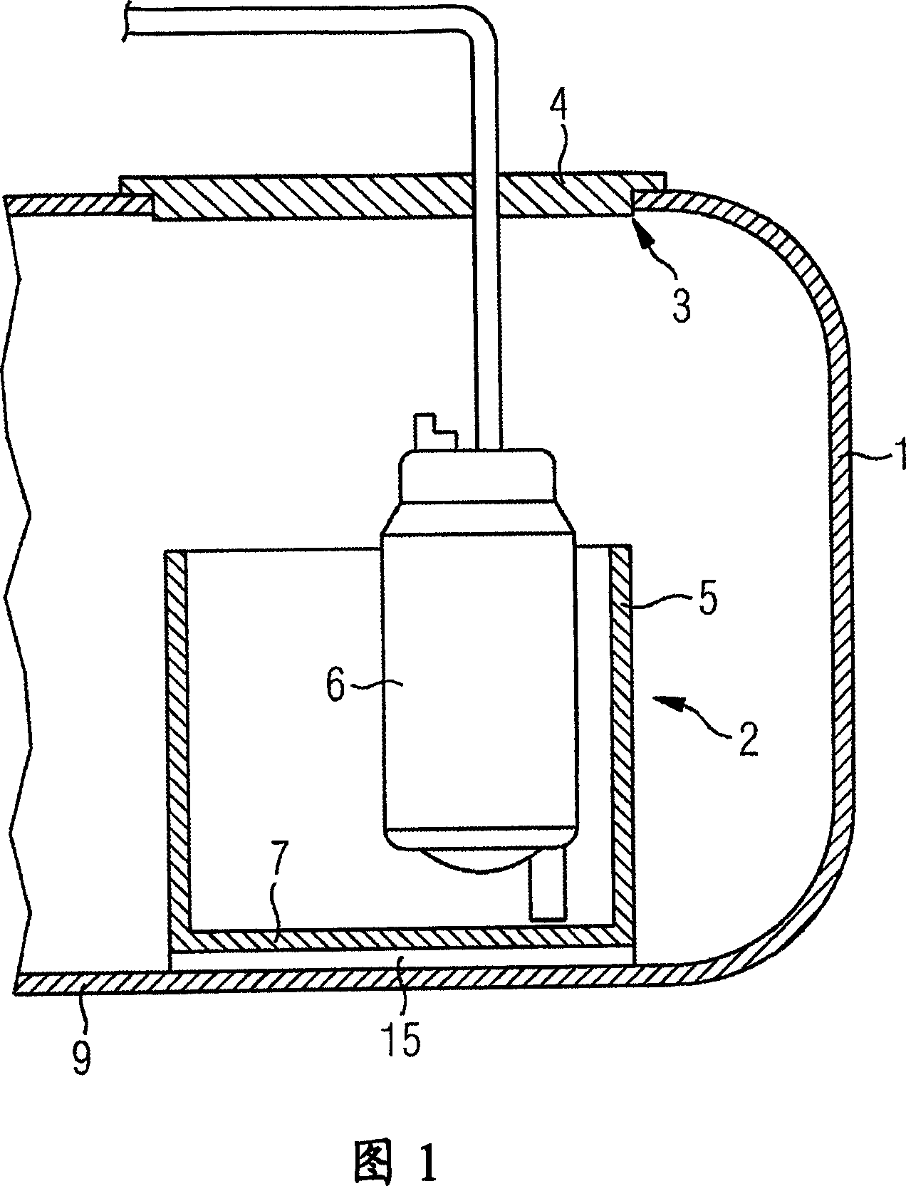
[0022] The fuel tank 1 shown in FIG. 1 includes a delivery unit 2. The delivery unit 2 is inserted into the opening 3 of the fuel tank 1, wherein a flange 4 closes the opening 3 in the fuel tank 1. The delivery unit 2 includes an anti-swirl box 5 for accommodating fuel and a fuel pump 6 arranged in the anti-swirl box, and the fuel pump delivers the fuel to an internal combustion engine of a motor vehicle, not shown. The conveying unit 2 is placed on the bottom 9 of the oil storage tank by using the swirl box 5.

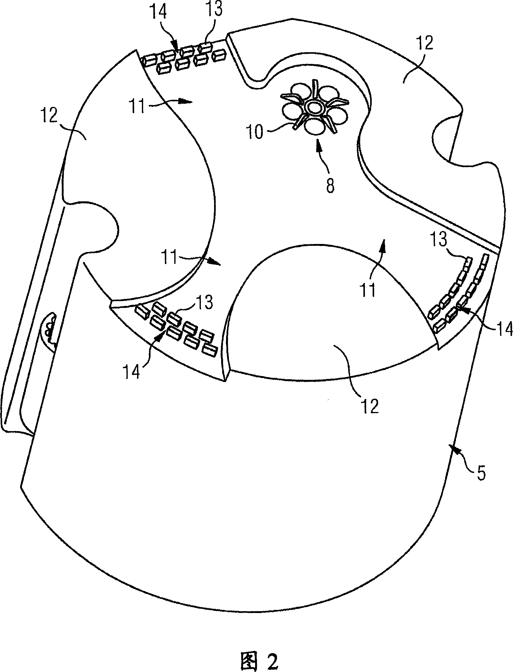
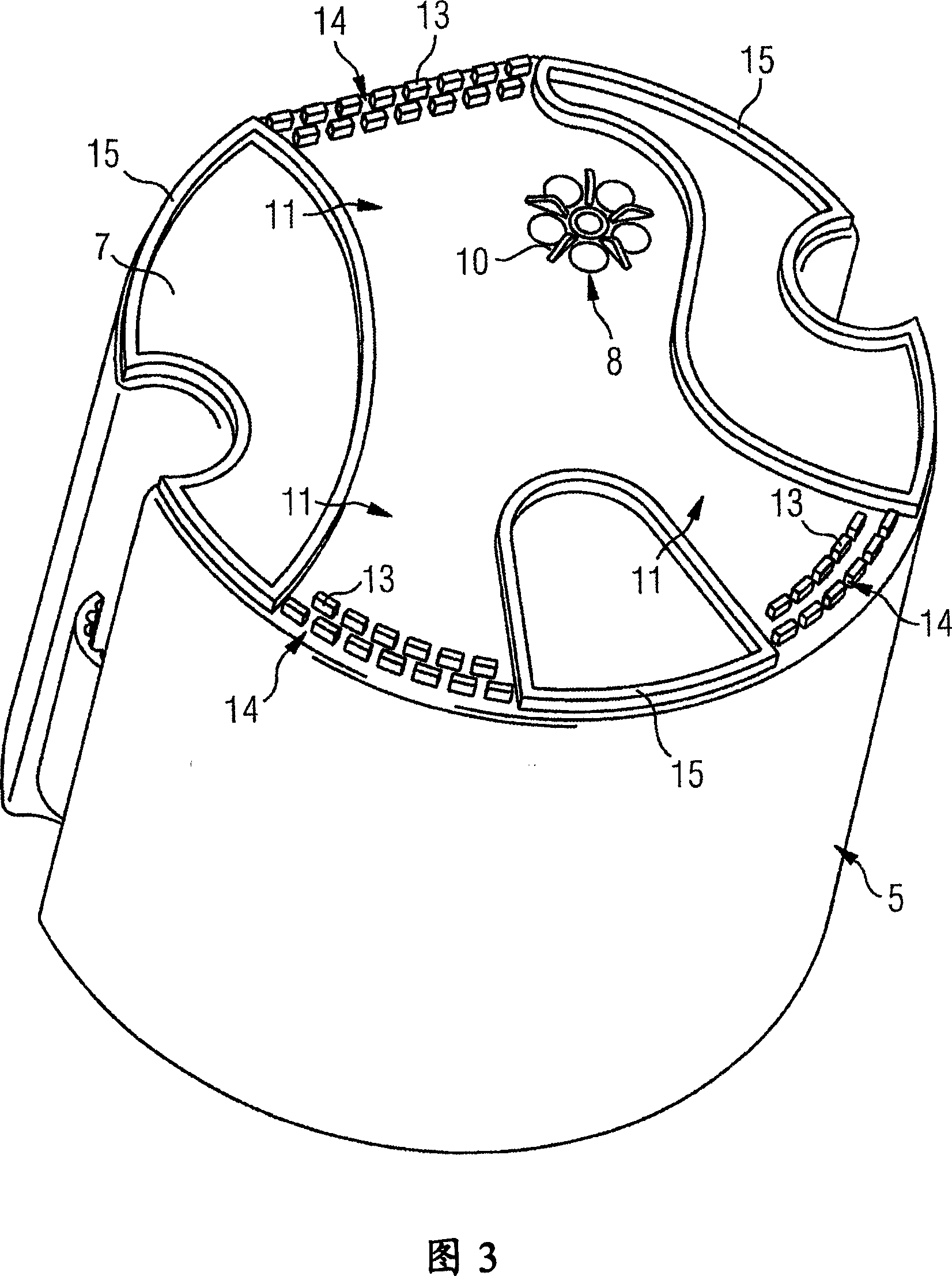
[0023] FIG. 2 shows a top view of the bottom 7 of the swirl box 5 shown in FIG. 1. The bottom 7 has an inlet 8 through which fuel from the fuel tank 1 reaches the swirl box 5. The inlet 8 has a spacer 10. A pipe 11 is provided in the bottom 7 of the swirl box 5, which is designed as an inwardly offset area. The pipe 11 extends from the radially outer edge of the bottom 7 of the swirl box 5 to the inlet 8, wherein the pipe connected to the radially outer edge has a tapered...


PUM


Abstract

The invention relates to a delivery unit (2) comprising a swirl pot (5), a fuel pump (6) that is located in said pot and a filter (14) that is situated on the floor (7) of the swirl pot (5), said filter being connected upstream of an inlet opening (8) that is located on the floor (7) of the swirl pot (5). Channels (11) are configured on the face of the swirl pot (5) that faces the floor of the tank (9), said channels being configured in such a way that fuel can flow from the periphery of the swirl pot (5) to the inlet opening (8). Moulded elements (13) that form filters (14) are situated in the channels (11).

Description

Technical field [0001] The present invention relates to a conveying unit, which has an anti-swirl box, a fuel pump arranged in the anti-swirl box, and a filter arranged on the bottom of the anti-swirl box, and the filter is placed in front of the anti-swirl box. Entrance on the bottom of the swirl box. The delivery unit is used to deliver the fuel in the fuel tank to the internal combustion engine of the motor vehicle. Background technique [0002] This type of delivery unit installed in the fuel tank has been disclosed. The dirt contained in the fuel can reach the fuel pump and damage the fuel pump. In order to protect the fuel pump from these dirt, the fuel drawn by the fuel pump is filtered. For this reason, the fuel pump is pre-installed with a coarse filter, so that particles that may cause damage to the fuel pump are kept away from the pumping area of ​​the fuel pump. [0003] The filter disclosed herein is a separate component that is installed on the bottom of the anti-sw...

Claims


Application Information

Patent Timeline
Patent Type & Authority Applications(China)
IPC IPC(8): B60K15/077F02M37/22
CPCB60K2015/03105B60K2015/03236B60K15/077
Inventor 托尔斯滕·巴尔茨
Owner CONTINENTAL AUTOMOTIVE GMBH
Why Eureka
Try Eureka