
Wireless temperature sensors

A wireless temperature and sensing device technology, applied in the field of electronic information, can solve the problems of high equipment cost, high labor cost, and low detection temperature accuracy

Inactive Publication Date: 2007-02-28
胡淼龙
View PDF0 Cites 3 Cited by
  • Summary
  • Abstract
  • Description
  • Claims
  • Application Information

AI Technical Summary

Problems solved by technology

At present, the temperature measurement of high-voltage power transmission and transformation lines and live equipment usually uses temperature-measuring wax chips, but the wax chips can only measure the temperature qualitatively, and must be manually inspected periodically to determine whether it is overheated according to the melting conditions of the wax chips with different melting temperatures , Whether a fault occurs, the advantage of this method is that it is simple, the equipment cost is very low, the disadvantage is that the accuracy of temperature detection is too low, the real-time performance is too poor, the manual workload is too large, and the labor cost is very high
There is also a method of infrared non-contact temperature measurement for temperature detection. The accuracy of infrared non-contact temperature measurement is high, but most occasions must be manually inspected regularly. The advantage of this method is that it is very intuitive and can directly find the fault point. The disadvantage is that It must be detected visually, the use occasion is greatly restricted, the equipment cost is high, the real-time performance is too poor, the manual workload is too large, and the labor cost is high

Method used


Image

  • Wireless temperature sensors
  • Wireless temperature sensors
  • Wireless temperature sensors

Examples


Embodiment Construction

[0010] The present invention will be further described below in conjunction with accompanying drawing by embodiment:

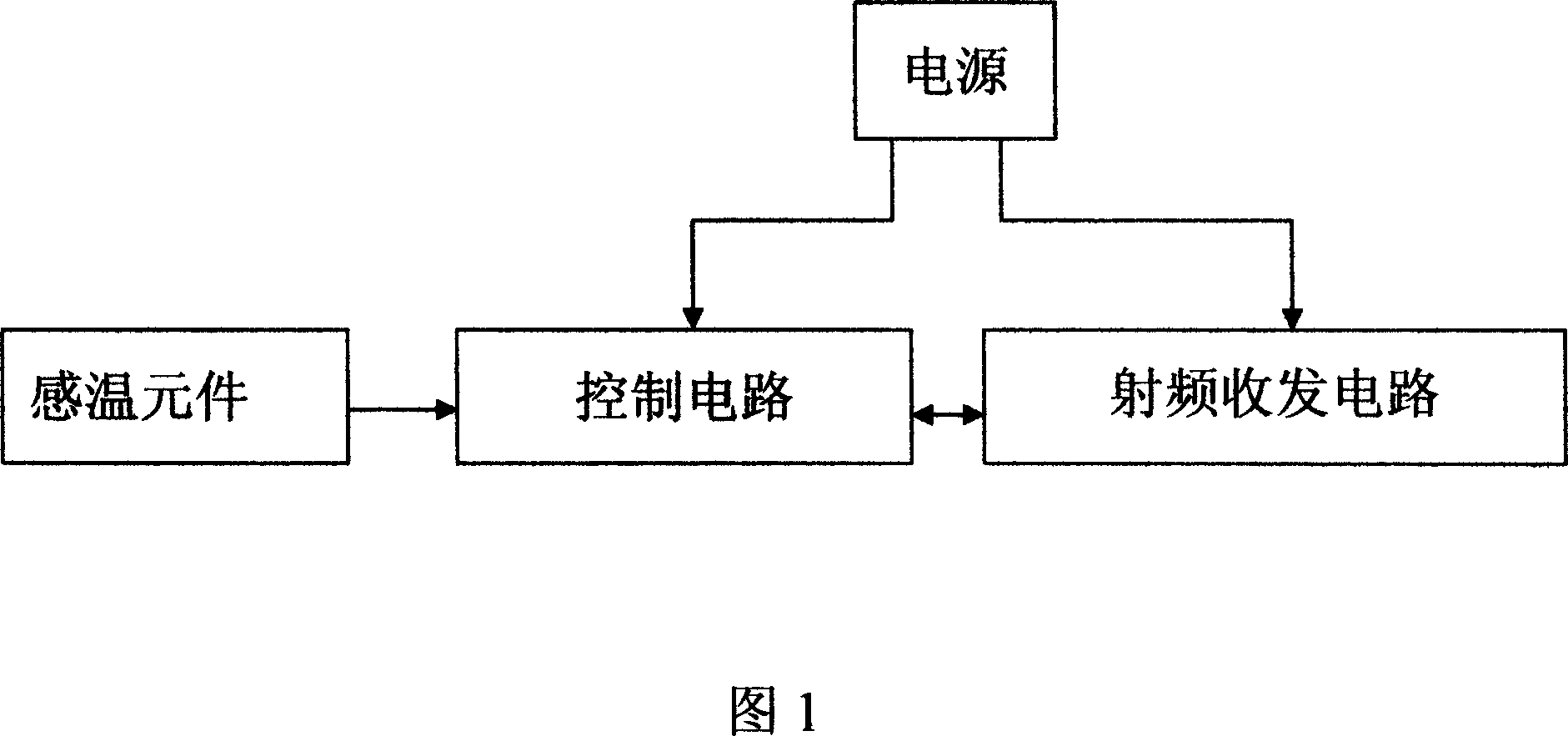
[0011] As shown in Figure 1 and Figure 2, the wireless temperature sensor is composed of a power supply, a temperature sensing element, a control circuit, and a radio frequency transceiver circuit. The control circuit is composed of a low-power high-speed CPU and an RC oscillator. circuit, 16MHZ crystal oscillator and antenna, the above-mentioned temperature sensing element is at the analog signal input end of the CPU, and the SPI port of the CPU is connected with the SPI port of the 2.4GHZ radio frequency transceiver integrated circuit.

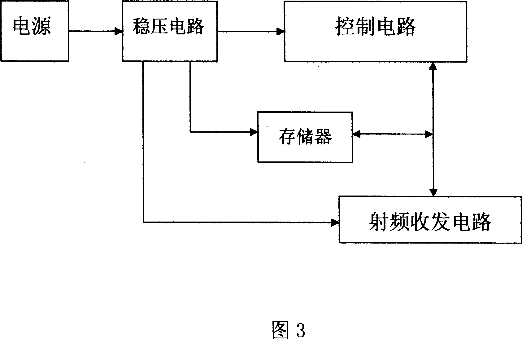
[0012] As shown in Figure 3 and Figure 4, the wireless temperature signal collector is composed of a power supply, a voltage regulator circuit, a control circuit, a radio frequency transceiver circuit and a memory, the control circuit is composed of a low-power high-speed CPU and a 10MHZ crystal oscillator, and the radio freq...


PUM


Abstract

The invention relates to a wireless temperature sensing device, which comprises a wireless temperature sensor and a wireless temperature signal collector, wherein said wireless temperature sensor is formed by power source, temperature sensing element, control circuit, and radio receiving / sending circuit; the temperature sensing element is connected to the analogue signal input of control circuit; the control circuit via SPI bus is connected to the radio receiving / sending circuit; the wireless temperature signal collector is formed by power source, stabilizing circuit, control circuit, radio receiving / sending circuit and memory; the control circuit via SPI bus reads and writes the radio receiving / sending circuit and memory; the wireless temperature sensing device operates via preset manage control software, uses TDMA boost frequency expansion and frequency boost mode; and it will sleep after sending one information, to be set as the intermission working mode whose occupy ratio is above 1000. Therefore, the invention has low cost, high reliability and online property.

Description

technical field [0001] The invention belongs to the field of electronic information, in particular to a wireless temperature sensing device used for temperature monitoring of places that are difficult to reach manually. Background technique [0002] High-voltage power transmission and transformation lines will cause heat due to various reasons, and may also be caused by faults. In order to ensure the safe operation of the power grid, the temperature of related lines and equipment must be monitored and measured. At present, the temperature measurement of high-voltage power transmission and transformation lines and live equipment usually uses temperature-measuring wax chips, but the wax chips can only measure the temperature qualitatively, and must be manually inspected periodically to determine whether it is overheated according to the melting conditions of the wax chips with different melting temperatures , Whether a fault occurs, the advantage of t...

Claims


Application Information

Patent Timeline
Patent Type & Authority Applications(China)
IPC IPC(8): G01K1/02G08C17/02G01K1/024
Inventor 胡淼龙
Owner 胡淼龙
Learn More