Spindle nose for processing central machine

A technology of machining center and machine head seat, applied in metal processing equipment and other directions, can solve the problems of not smooth processing surface, affecting workpiece machining precision, unable to bear torque, etc., to improve cutting rigidity and machining precision, and reduce machining interference. Area, the effect of reducing vibration frequency

Inactive Publication Date: 2007-02-28
SHE HONG INDAL
View PDF0 Cites 1 Cited by
  • Summary
  • Abstract
  • Description
  • Claims
  • Application Information

AI Technical Summary

Problems solved by technology

[0007] Referring to Fig. 5, since the aforementioned line rail 13 and the aforementioned slider 14 are respectively arranged on the two side surfaces 121 of the shaft seat 12, when the shaft seat 12 is displaced along the X-axis direction to bear the force FX, the aforementioned line rail 13 will Because of the direction of the acting force FX, the aforementioned slider 14 can only bear the moment in the direction of MB and MC respectively, but cannot bear the moment in the direction of MA.
Referring to Fig. 6, when the shaft seat 12 is displaced along the Y-axis direction and bears the force FY, the aforementioned line rail 13 can only bear the moments in the direction of MA and MC because of the direction of the force FY, but Unable to withstand moment in MB direction
Therefore, the shaft seat 12 is prone to vibration during processing, and the cutting rigidity is insufficient, so that the processed surface of the workpiece is not smooth enough, which seriously affects the processing precision of the workpiece.

Method used


Image

  • Spindle nose for processing central machine
  • Spindle nose for processing central machine
  • Spindle nose for processing central machine

Examples


Embodiment Construction

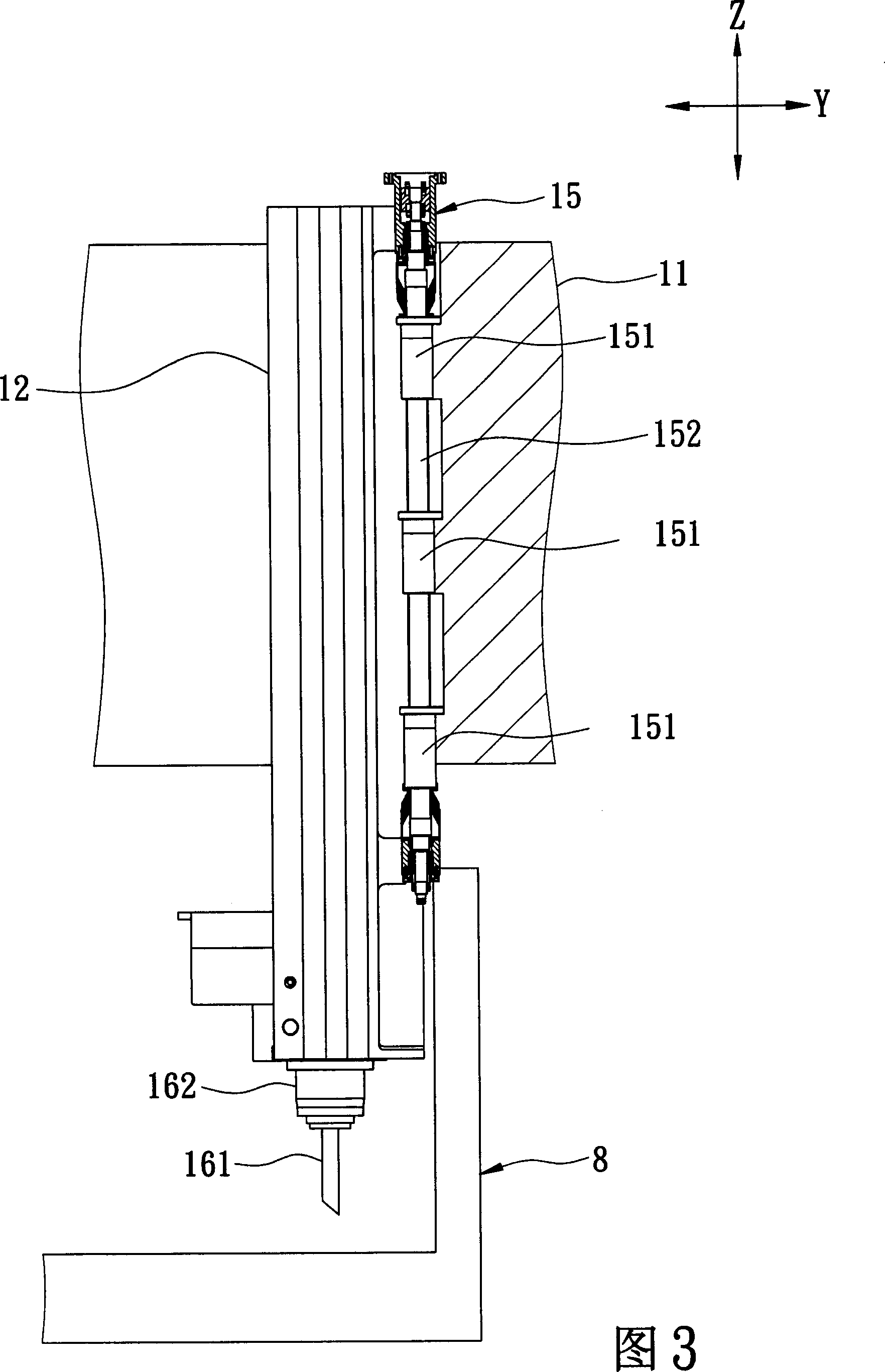
[0033] Referring to Fig. 7, Fig. 8, and Fig. 9, the preferred embodiment of the shaft head of the machining center machine of the present invention includes: a headstock 2, a shaft seat 3, a line rail group 4, a slide block group 5, a drive Unit 6 and a processing unit 7.

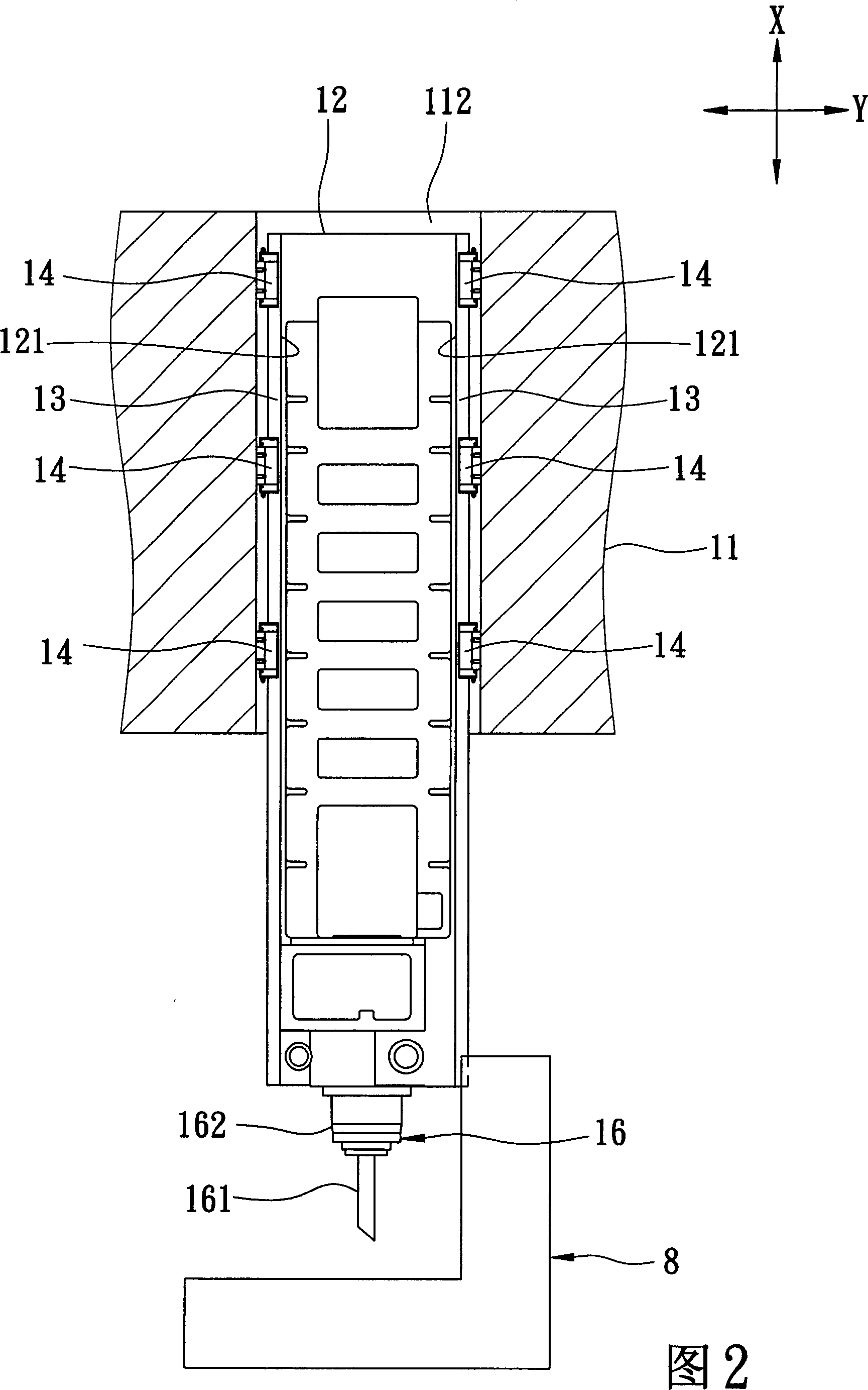
[0034] The headstock 2 has a track groove 22 formed on a front surface and extending along a Z-axis direction.

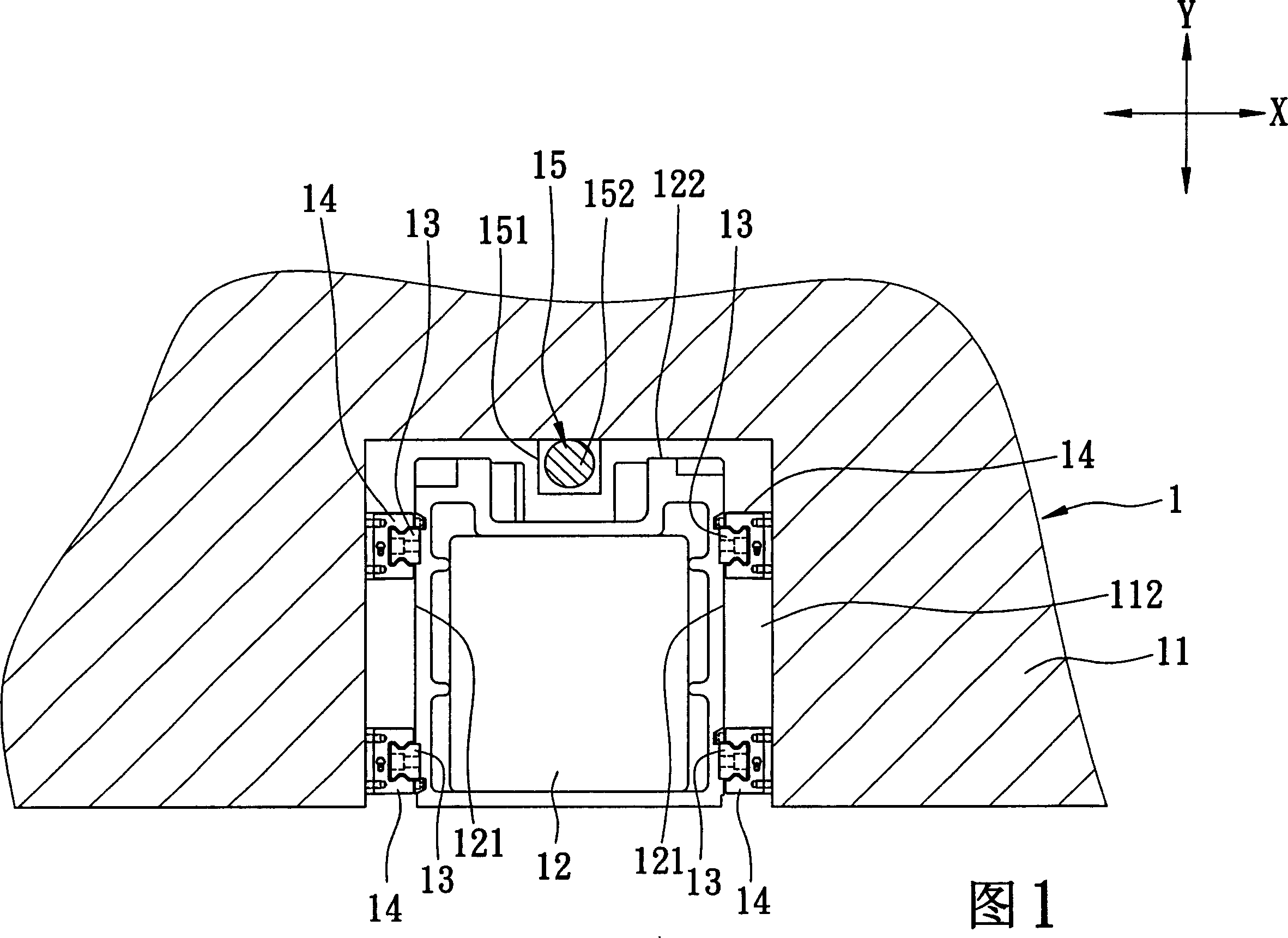
[0035] The shaft seat 3 passes through the track groove 22 along the Z-axis direction, and has a first groove 32 and a second groove 33 formed on opposite sides 31 and extending along the Z-axis direction, and formed on the A concave portion 35 and two third grooves 36 extend along the Z-axis direction on the other side 34 .

[0036] The track set 4 has a first track 41 , a second track 42 and two third tracks 43 . The first and second line rails 41, 42 and the aforementioned third line rail 43 are respectively buried in the first and second slots 32, 33 and the aforementioned third slot 36 of ...


PUM


Abstract

The invention discloses a shaft head of manufactured center machine, which comprises the following parts: frame head seat, which possesses rail groove on the positive surface to extend along axle Z, shaft seat, which pierces the rail groove along axle Z with at least one first groove channel and at least one second groove channel on two opposite sides along Z shaft, line rail group, which consists of at least one first line rail and at least one second line rail in the first and second groove channel separately along axle Z, sliding group, which consists of multiple first and second sliding blocks, wherein the first and second sliding blocks are fixed on two groove walls, which pierces the first and second groove channel to mate the first and second line rails.

Description

【Technical field】 [0001] The invention relates to a shaft head of a machining center, in particular to a shaft head of a machining center which can be lifted up and down along the Z-axis direction. 【Background technique】 [0002] Referring to Fig. 1, Fig. 2 and Fig. 3, the spindle head 1 of a general machining center mainly includes a headstock 11, a shaft seat 12, two pairs of line rails 13, a plurality of sliders 14, a driving unit 15 and a machining center. Unit 16. [0003] The headstock 11 has a track groove 112 formed on a front surface and extending along a Z-axis direction. The shaft seat 12 passes through the rail groove 112 and has two opposite side surfaces 121 and a back surface 122 facing the groove wall of the rail groove 112 . The aforementioned wire rail 13 is fixed on the two side surfaces 121 of the shaft seat 12 . The aforementioned sliding blocks 14 are respectively fixed on two opposite groove walls of the rail groove 112 and slide with the aforementi...

Claims


Application Information

Patent Timeline
IPC IPC(8): B23B19/02
Inventor 陈建智
Owner SHE HONG INDAL
Why Eureka
Try Eureka