
Multistage heading machine

A multi-stage, shape machine technology, applied in the direction of presses, forging presses, forging presses, etc.

Active Publication Date: 2007-02-14
DAIDO MACHINERY
View PDF1 Cites 4 Cited by
  • Summary
  • Abstract
  • Description
  • Claims
  • Application Information

AI Technical Summary

Problems solved by technology

[0006] That is, the present invention is made in view of the above-mentioned problems in the above-mentioned prior art, and it is proposed to appropriately solve the problems. Manufacture and obtain tiny parts without poor transfer or poor forming

Method used


Image

  • Multistage heading machine
  • Multistage heading machine
  • Multistage heading machine

Examples


Embodiment 1

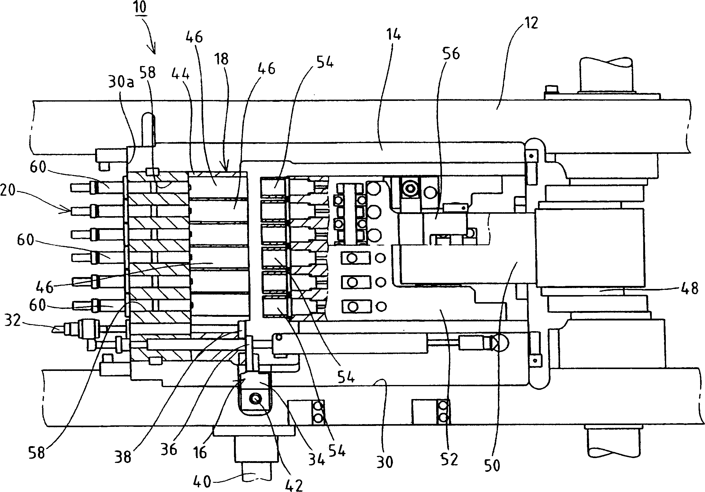
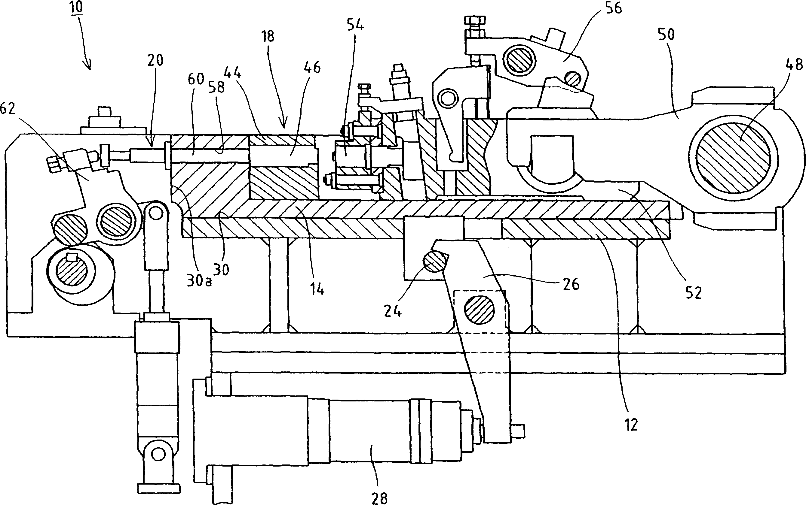
[0032] figure 1 The multi-stage press forming machine 10 of the first embodiment shown includes a mounting table 14 that can be detached from the device frame 12, and the mounting table 14 is equipped with a cutting mechanism 16 and a multi-stage pressing mechanism 18, which will be described later. , The extrusion mechanism 20 and the transfer mechanism 22 are boxed. The installation table 14, such as figure 2 As shown, the engaging member 24 is arranged, and the engaged member 26 that can be engaged and disengaged with respect to the engaging member 24 is rotatably arranged on the device frame 12. On the lower end of the pivot support of the engaged member 26, a hydraulic cylinder 28 as an operating mechanism arranged on the device frame 12 is connected, and the hydraulic cylinder 28 exerts a forward or reverse action. The force causes the upper end portion of the pivot support portion of the engaged member 26 to move (tilt movement) between the engagement position with respe...

Embodiment 2

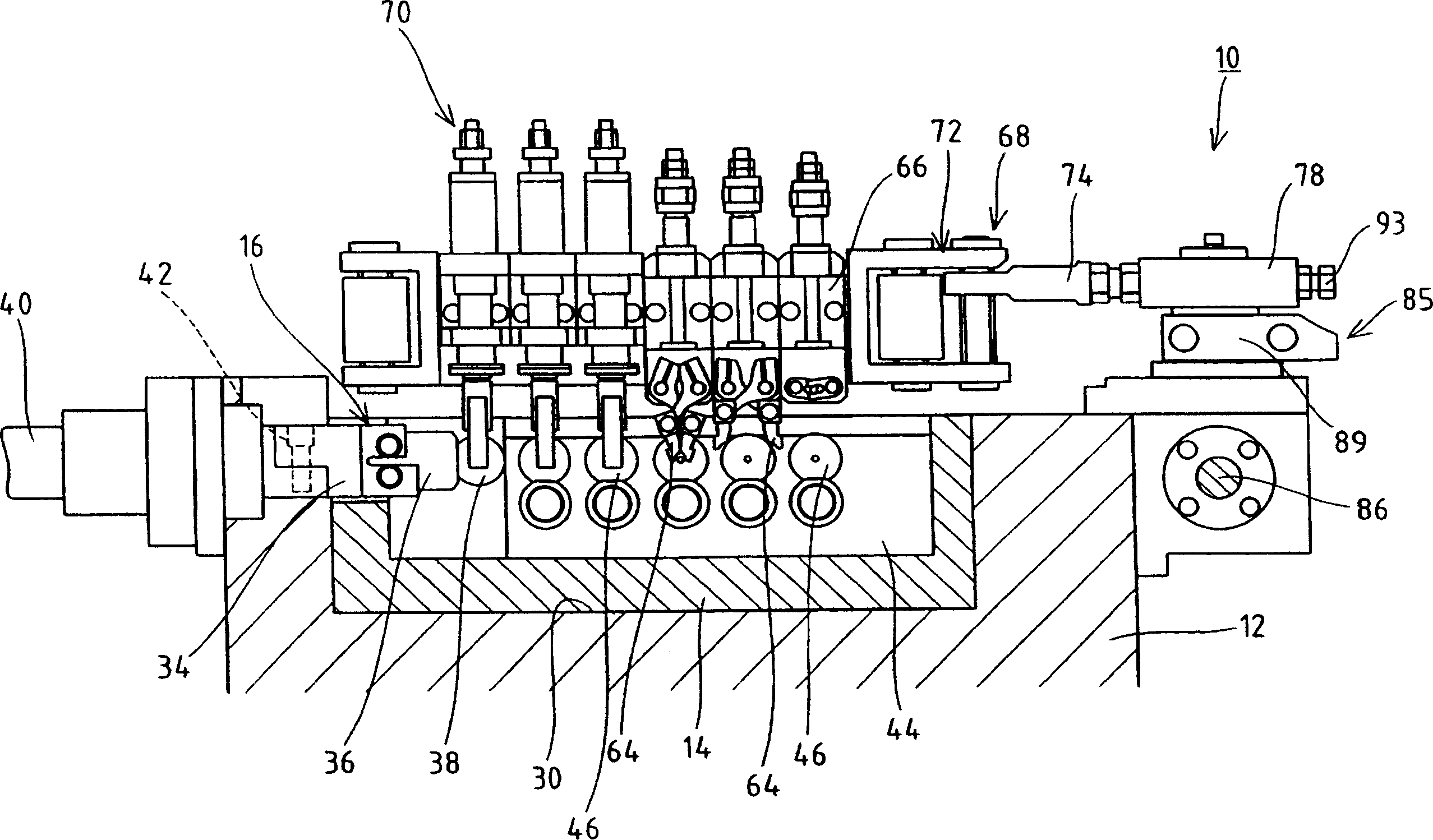
[0057] Figure 7 and Figure 8 It is a diagram showing another example of the eccentric structure used in the multi-stage press forming machine of the second embodiment. The basic structure is the same as that of the first embodiment, so only the different parts will be described. The existing same components The same reference numerals are indicated.

[0058] In this second embodiment, the drive mechanism 85 is provided with a swinging member 89 arranged on the first drive shaft 88, which is vertically arranged at a position eccentric from the arrangement position of the first drive shaft 88 and protrudes by a predetermined height.轴95. In addition, the swing shaft 95 swings in a circular arc shape with the drive shaft 88 as the center along with the forward and reverse rotation of the first drive shaft 88 within a desired angle range. On the other hand, the eccentric sleeve 96 is externally fitted on the swing shaft 95 through the bearings 92 and 92 in a relatively rotatable stat...


PUM

PropertyMeasurementUnit
diameteraaaaaaaaaa

Abstract

The invention provides a multistage heading machine capable of manufacturing micro parts without producing defective transportation and defective molding by swinging the chuck of a carrying means at an accurate stroke. A drive mechanism (85) operating a swing mechanism is disposed on a first drive shaft (88) forwardly and reversely rotated by the forward and backward movements of a drive rod (86) so that an operating member (89) can be rotated integrally with each other. An eccentric shaft (90) is disposed in the operating member (89) eccentrically from the first drive shaft (88), and the eccentric shaft (90) is swung in an arc shape as the first drive shaft (88) is rotated in the forward and reverse directions. The connection member (78) of the swing mechanism is connected to a sleeve (91) fitted onto the eccentric shaft (90), and the chuck swings between adjacent dies according to the swing movement of the eccentric shaft (90). Since a separate distance (L) between the axis (C5) of the first drive shaft (88) and the center (C4) of a through-hole (78a) in the connection member (78) is changed by rotating the eccentric shaft (90), the swing stroke of the chuck can be adjusted.

Description

Technical field [0001] The present invention relates to a multi-stage press forming machine, which is provided with a plurality of parallel die sets composed of dies and punches, and is formed by sequentially transporting raw materials processed by each die set through a clamp. Background technique [0002] A multi-stage press forming machine (for example, refer to Patent Document 1) that is provided with a plurality of die sets composed of a pair of dies and punches, and uses these die sets to sequentially press and form metal materials in stages (for example, refer to Patent Document 1). It has the following basic structure. In other words, the device frame is provided with a cutting mechanism that cuts the wire rod supplied by the feeding device to a predetermined size from the front end thereof. The front end of the device frame is provided with a punching module, and a plurality of punching dies are arranged horizontally in a row while keeping a certain interval on the punch...

Claims


Application Information

Patent Timeline
Patent Type & Authority Applications(China)
IPC IPC(8): B21K27/00B21J13/08B30B13/00B21J9/02B21K27/04B21K31/00
CPCB21J9/022B21K27/04
Inventor 大原尚
Owner DAIDO MACHINERY
Learn More