Machine core of paper pulverizer

A paper shredder and machine core technology, which is applied in the direction of grain processing, etc., can solve the problems of reducing the life of the paper shredder, paper jams, paper belts, etc., and achieve the effect of ideal shredding effect, large number of shredded paper, and less failure.

Inactive Publication Date: 2007-02-14
黄铭玉
View PDF1 Cites 9 Cited by
  • Summary
  • Abstract
  • Description
  • Claims
  • Application Information

AI Technical Summary

Problems solved by technology

However, when the above-mentioned electric shredder shreds a large amount of paper at one time, paper jams, paper jams, and paper strips often occur. Not only the shredding effect is not ideal, but also the machine is prone to failure and reduces the life of the shredder.

Method used


Image

  • Machine core of paper pulverizer
  • Machine core of paper pulverizer
  • Machine core of paper pulverizer

Examples


Embodiment Construction

[0015] The present invention will be further described in detail below with reference to the embodiments of the drawings.

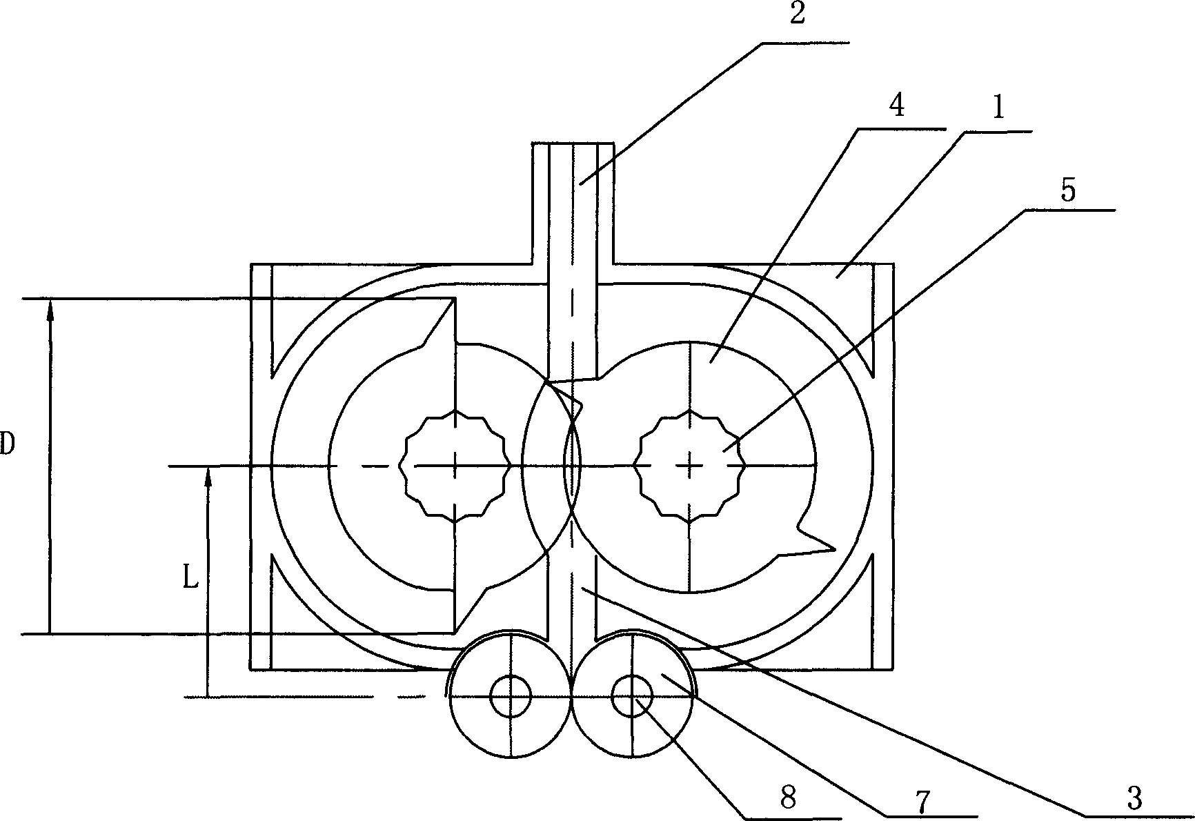
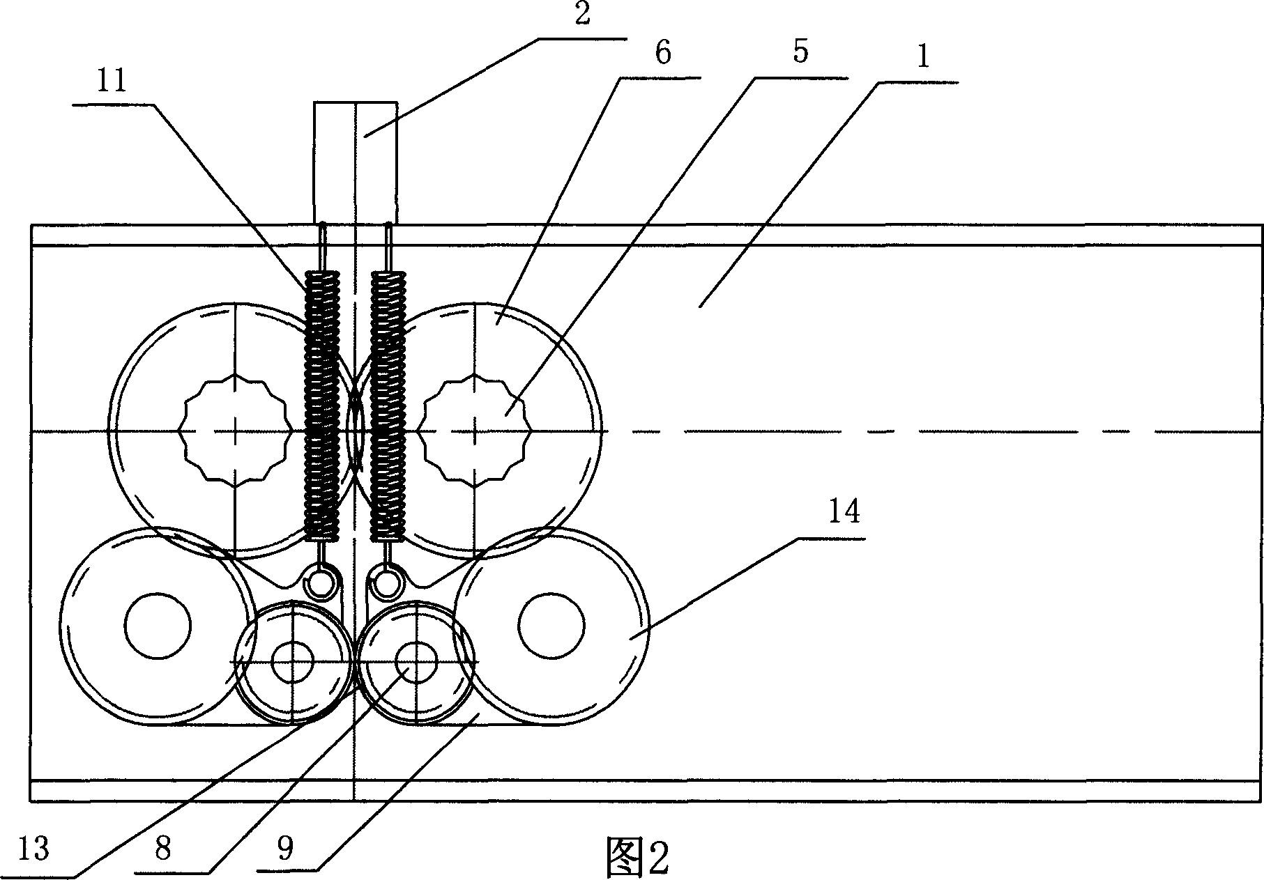
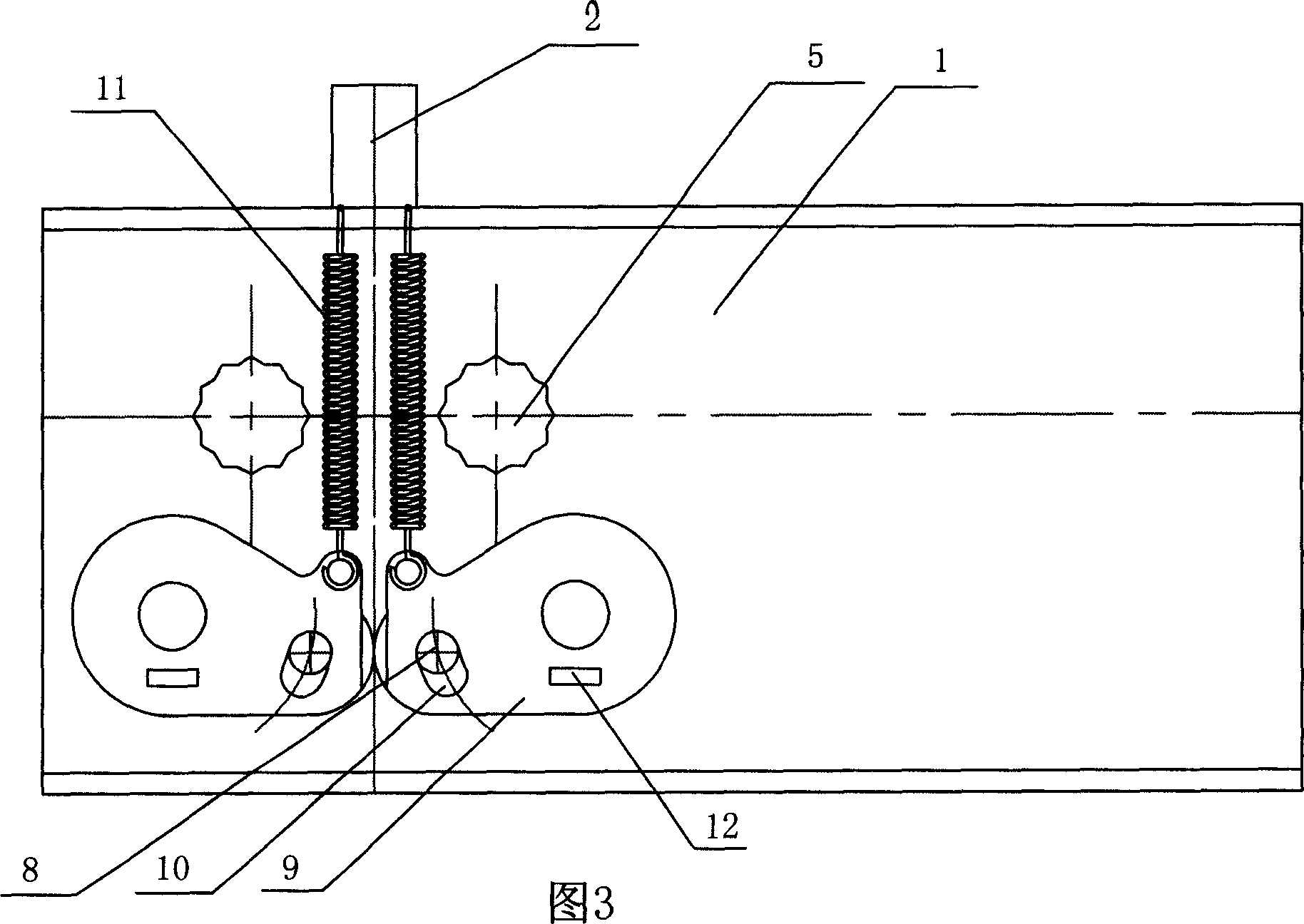
[0016] As shown in the figure, the core of a paper shredder includes a core body 1. A paper inlet 2 and a paper outlet 3 are provided on the core body 1, and a roller is arranged between the paper inlet 2 and the paper outlet 3. A knife shredding mechanism, which includes two hob shafts 5 provided with hobs 4, one side of the hob shaft 5 is coaxially provided with a hob gear 6, and the other end of the hob shaft 5 is connected with a driving mechanism (not shown in the figure) Show), there are two lead rollers 7 behind the paper exit 3, the lead rollers 7 are coaxially arranged on the lead roller shaft 8, the two ends of the lead roller 7 are provided with two swing arms 9, the core 1 An arc-shaped slot 10 is provided on it, and the paper guide roller shaft 8 passes through the arc-shaped slot 10 and is axially connected to the swing arm 9. A swing arm spring...


PUM


Abstract

The paper shredder core includes one shredder body with paper inlet and paper outlet and one paper shredding hob mechanism including two hob shafts with hobs, and features its paper guiding mechanism set in the paper outlet and synchronous driving mechanism set between paper guiding mechanism and the paper shredding hob mechanism to force the shredded paper exhausted into the shredded paper tub. It has good paper shredding effect, no jamming, less fault and long service life.

Description

Technical field [0001] The invention relates to a paper shredder, in particular to a core of the paper shredder. Background technique [0002] The core of the paper shredder is the core component of the paper shredder. The core of the existing paper shredder is mainly composed of a core provided with a paper inlet and a paper outlet, and a core set between the paper inlet and the paper outlet. The hob shredder mechanism. For example, the Chinese utility model patent No. 200420071230.9 authorized by the announcement on December 21, 2005 discloses an electric paper shredder, including a body and a paper cassette, the body includes a housing and a double-roller paper shredder mechanism, the double-roller paper shredder mechanism A paper feeding device is provided on the upper rear side of the paper cassette, the paper cassette is installed obliquely above the paper feeding device; the paper feeding device includes a reel with rubber wheels installed between the two sides of the plat...

Claims


Application Information

Patent Timeline
Patent Type & Authority Applications(China)
IPC IPC(8): B02C18/16B02C18/18B02C18/22B02C18/24
Inventor 黄铭玉
Owner 黄铭玉
Why Eureka
Try Eureka