


Quick Research
Generate reliable direction feasibility study reports for your R&D in just a few steps.

Technical Q&A
Discover and master advanced knowledge NOW. Basics, ideas, possibilities, all at once.

Find Solutions
As an expert in R&D theories, this can generate solutions to your technical problems instantly.

Evaluate Feasibility
Analyze your overall solution with one click, know your potential R&D risks in advance.

Monitor Landscape
Get weekly tech updates, stay abreast of the latest tech innovations and key insights.
Compact disk sheet placing shelf
A technology for placing racks and optical discs, applied to carrier storage devices, instruments, flat record carrier containers, etc., can solve the problems of increasing test costs, and achieve the effect of saving operating time and efficient picking and placing
- Summary
- Abstract
- Description
- Claims
- Application Information
AI Technical Summary
Problems solved by technology
Method used
Image

Examples
no. 1 example
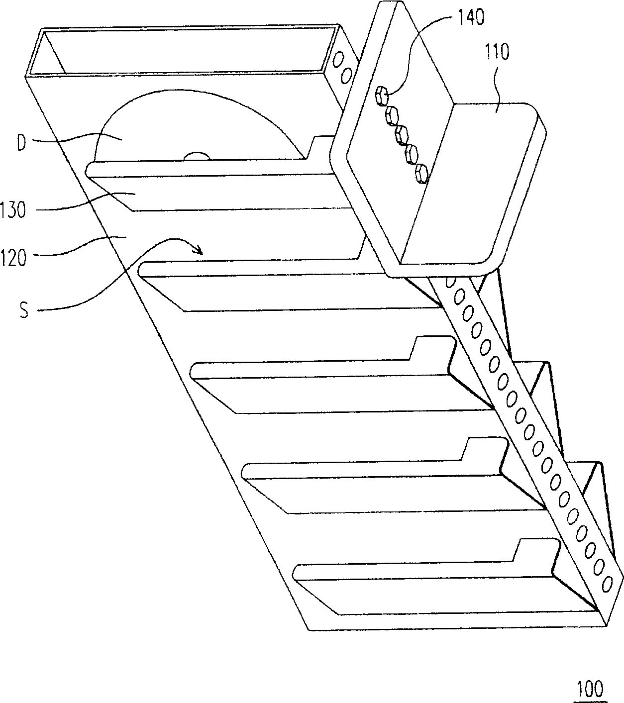
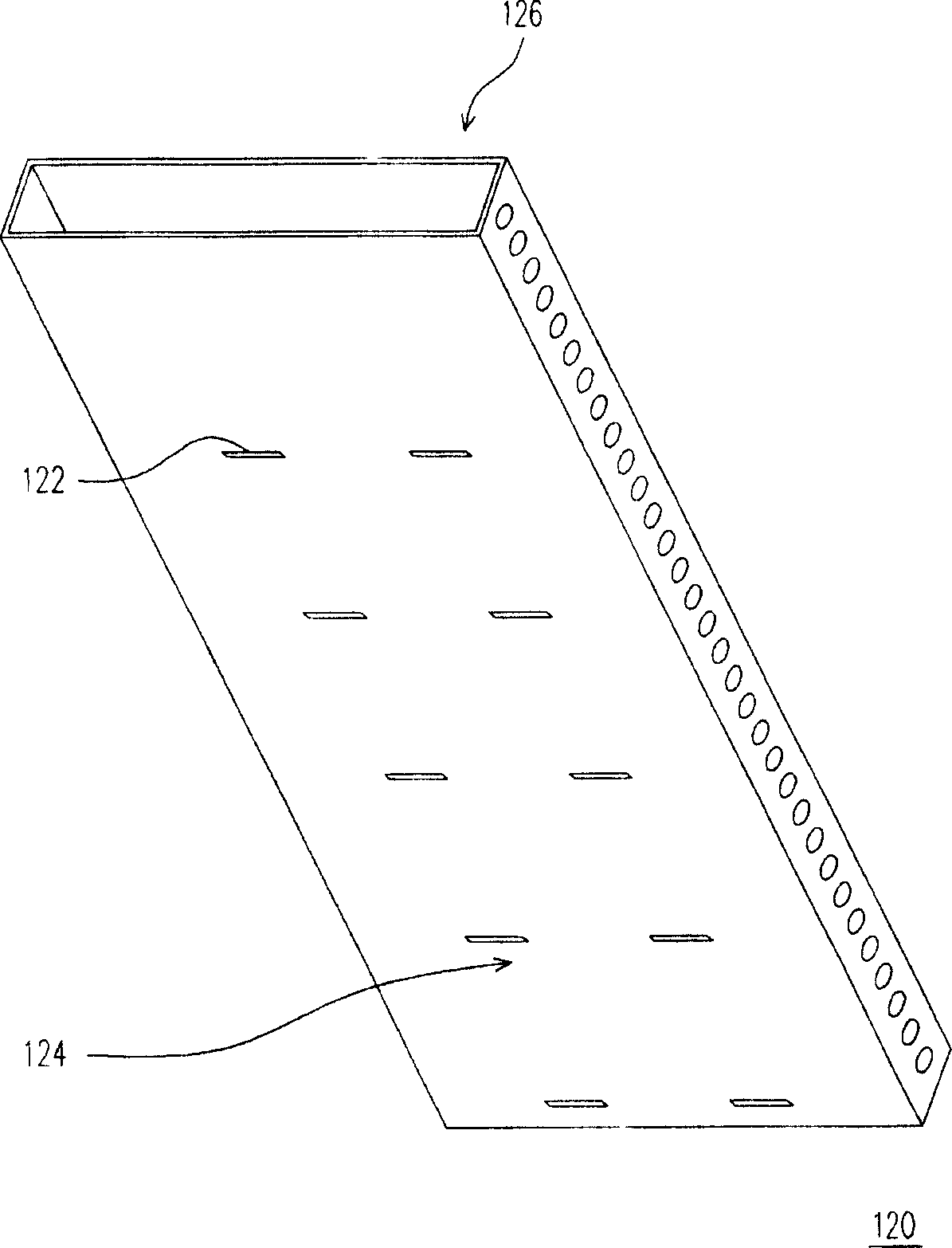
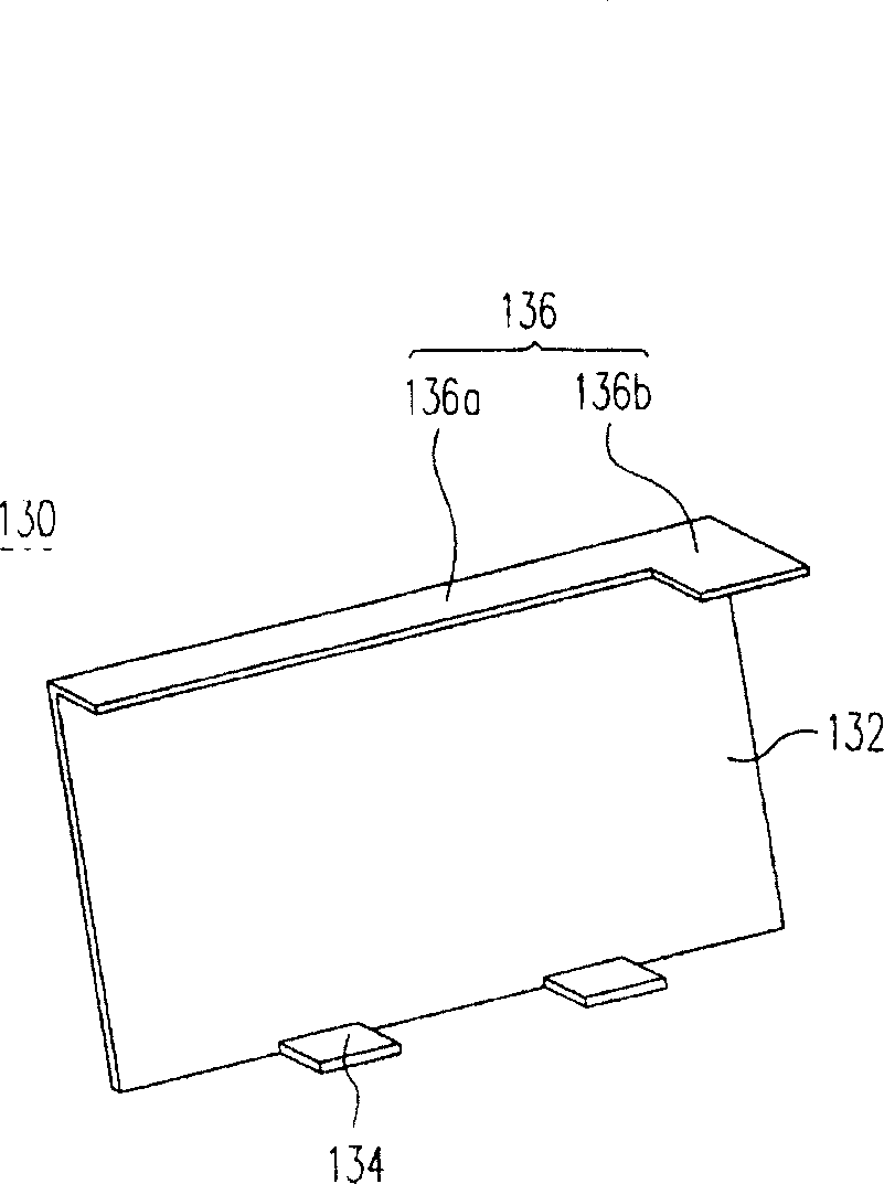
[0034] figure 1 is a schematic perspective view of an optical drive placement rack according to the first embodiment of the present invention, and figure 2 draw figure 1 A three-dimensional schematic diagram of the support frame. Please also refer to figure 1 and figure 2 , the optical disk storage rack 100 of this embodiment is suitable for storing at least one optical disk D. The optical disc placement rack 100 includes a base 110 , a supporting frame 120 and a plurality of receiving parts 130 , wherein the supporting frame 120 is connected to the base 110 , and the supporting frame 120 includes a plurality of first buckling portions 122 . In addition, a plurality of receiving parts 130 are connected to the supporting frame 120, and a plurality of accommodating spaces S are formed between the receiving parts 130 and the supporting frame 120 for accommodating the optical disk D. As shown in FIG.
[0035] Please refer to image 3 , which shows figure 1 A three-dimensi...
no. 2 example
[0041] Please refer to Figure 4A and Figure 4B , respectively depicting a three-dimensional schematic diagram of an optical disc storage rack according to the second embodiment of the present invention. The optical disc placement rack 200 of this embodiment is suitable for storing at least one optical disc D. As shown in FIG. The optical disc placing rack 200 includes a base 210 , a supporting frame 220 , a plurality of blocking seats 230 and a plurality of clamping modules 240 . Wherein, the supporting frame 220 is connected to the base 210 , and a plurality of blocking seats 230 are connected to the supporting frame 220 . In addition, a plurality of clamping modules 240 are respectively connected to the retaining seats 230 .
[0042] Each clamping module 240 includes a positioning member 242 and a plurality of positioning components 244 . Wherein, the positioning member 242 is connected to one of the stoppers 230 , the positioning member 242 has a plurality of disc cla...
PUM
 Abstract
Description
Claims
Application Information
 - R&D Engineer
- R&D Manager
- IP Professional
- Industry Leading Data Capabilities
- Powerful AI technology
- Patent DNA Extraction
Browse by: Latest US Patents, China's latest patents, Technical Efficacy Thesaurus, Application Domain, Technology Topic, Popular Technical Reports.
© 2024 PatSnap. All rights reserved.Legal|Privacy policy|Modern Slavery Act Transparency Statement|Sitemap|About US| Contact US: help@patsnap.com