Annular wire connection board

A ring-shaped and wire technology, which is applied in the direction of connection and electrical connection of printed components, current collectors, etc., can solve the problems of multi-channel wire winding, hidden danger of damage, and space occupation, so as to achieve small space occupation, avoid scratches and damage, reduce The effect of small volume

Active Publication Date: 2013-04-17
宁波景灯照明系统工程有限公司
View PDF8 Cites 1 Cited by
  • Summary
  • Abstract
  • Description
  • Claims
  • Application Information

AI Technical Summary

Problems solved by technology

When there are many lines that need to be transmitted between the stator and the rotor, multiple wires are entangled, which not only takes up space, but also poses a risk of damage

Method used


Image

  • Annular wire connection board
  • Annular wire connection board
  • Annular wire connection board

Examples


Embodiment Construction

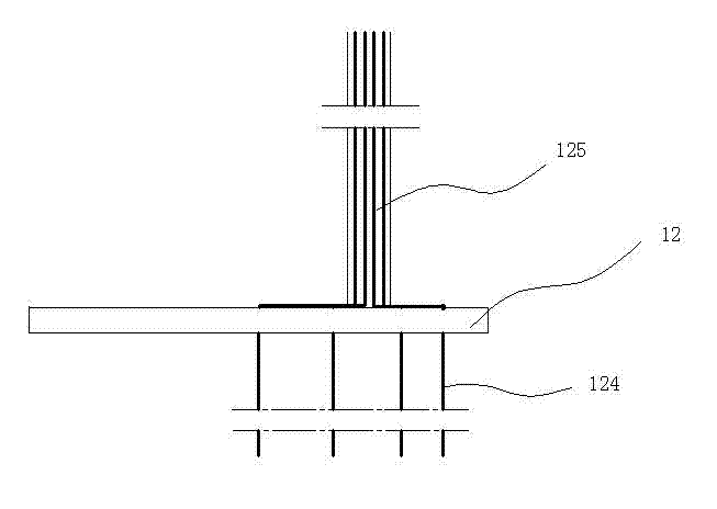
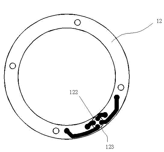
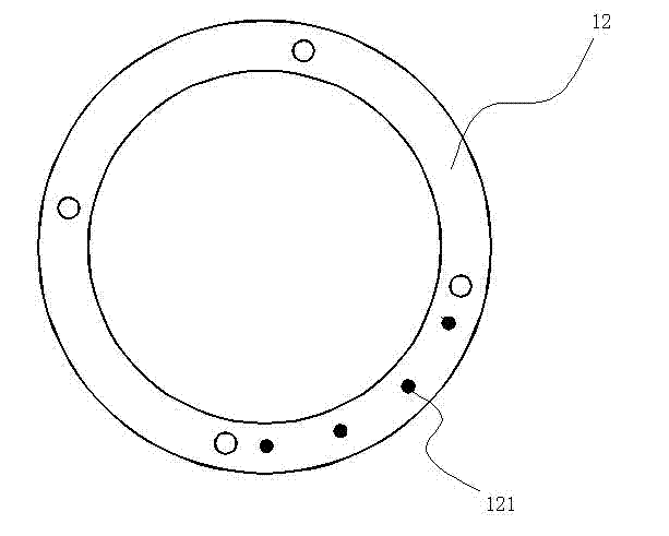
[0018] Such as Figures 1 to 7 As shown, a ring-shaped wire adapter plate of the present invention comprises:

[0019] A ring-shaped printed circuit board 12 arranged on the upper end of the rotor 10, four connection points A121 are distributed on the lower side of the ring-shaped printed circuit board 12, and each connection point A121 is connected to the collection area on the upper side of the ring-shaped printed circuit board 12 through a printed circuit Corresponding connection point B123 in 122, each connection point A121 is located directly above the corresponding lead wire 124 of the rotor conductive ring 22, and each of the lead wires 124 is electrically connected to the corresponding connection point A121 directly above, the collection area 122 Each connection point B123 in the wire bundle is electrically connected with the corresponding wire in the wire bundle 125 respectively;

[0020] An annular printed circuit board 12 arranged at the lower end of the stator 9, ...


PUM


Abstract

The invention discloses an annular wire connection board comprising an annular printing circuit board which is arranged at one end of a rotor or a stator, wherein at least two wiring points A are arranged on one surface of the annular printing circuit board, each wiring point A is connected with a corresponding wiring point B in a collection area on the other surface of the annular printing circuit board through a printing circuit, each wiring point A is respectively arranged just above or under a corresponding lead of a collecting ring, each lead is electrically connected with the corresponding wiring point A above or under the lead, and each wiring point B in the collection area is respectively and electrically connected with a corresponding lead in a lead beam. The annular wire connection board disclosed by the invention can integrally guide out dispersed leads or dispersively output the lead beam so that multipath leads are reasonably distributed; and therefore, the floor space of the leads is reduced and the damage hidden danger of the leads is eliminated.

Description

technical field [0001] The invention relates to a wiring board, in particular to a ring wire matching board used in conjunction with a collector ring. Background technique [0002] The collector ring is an electrical component responsible for the transmission of current between the stator (stationary body) and the rotor (rotating body). The existing collector ring includes: a conductive ring arranged on the rotor and rotating together with the rotor, and a brush arranged on the stator, through the contact between the brush and the outer peripheral surface of the conductive ring, to realize the contact between the rotor and the Transmission of current between the stators. When there are many lines that need to be transmitted between the stator and the rotor, multiple wires are entangled, which not only takes up space, but also poses a risk of damage. Contents of the invention [0003] The purpose of the present invention is to provide a ring-shaped wire adapter board, whi...

Claims


Application Information

Patent Timeline
IPC IPC(8): H01R39/02H05K1/11
Inventor 许杭旭孟元黔彭长慧
Owner 宁波景灯照明系统工程有限公司
Why Eureka
Try Eureka