Control method and device for DC load regulation and adjustment by AC
A technology of DC load and control method, which is applied in the direction of adjusting electric variables, control/regulation systems, instruments, etc. It can solve the problems that equipment cannot be re-controlled and improved, and modern technology cannot be implemented, so as to achieve diverse and flexible control methods and heat dissipation. Problem solving, increasing effectiveness of communication control methods
- Summary
- Abstract
- Description
- Claims
- Application Information
AI Technical Summary
Problems solved by technology
Method used
Image

Examples
Embodiment 1
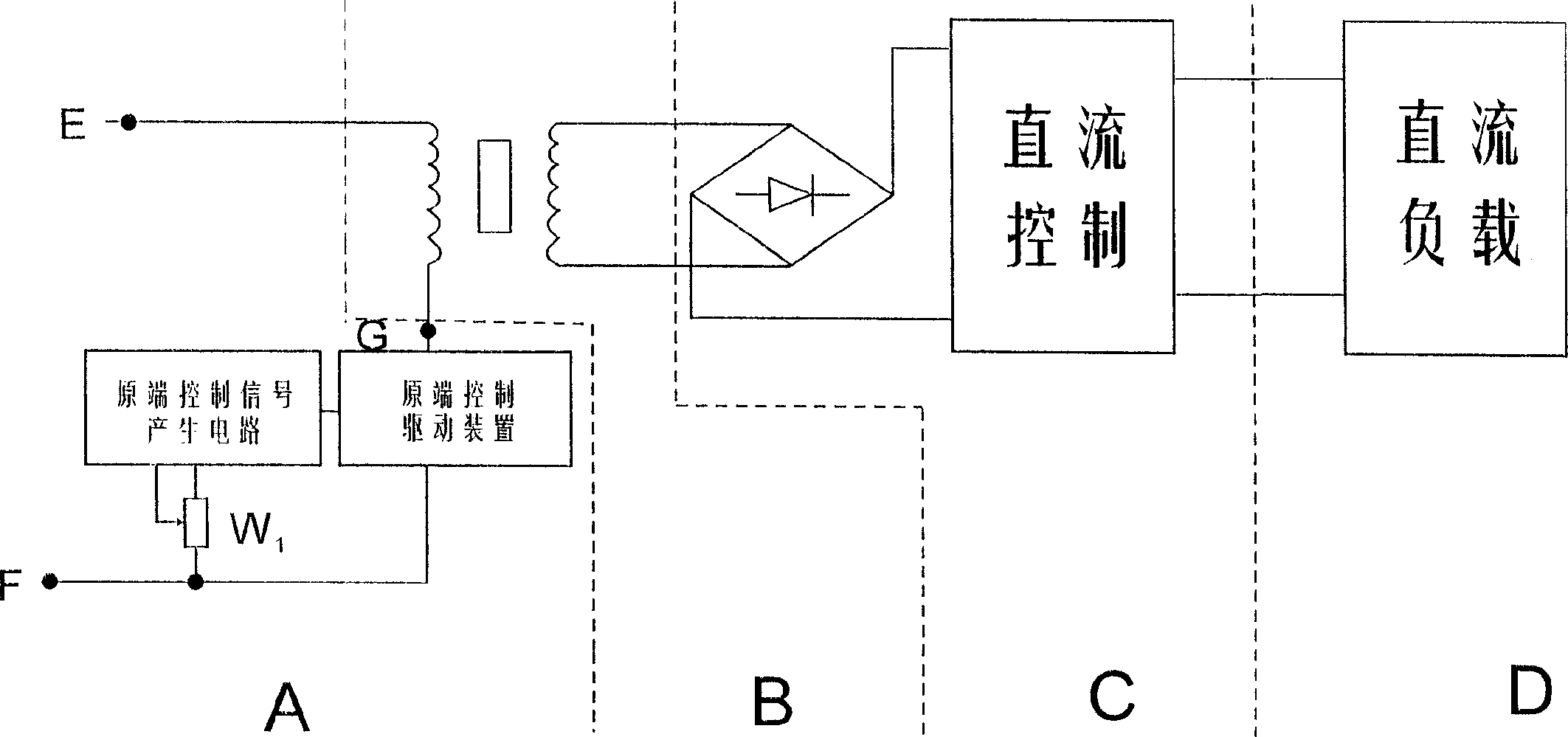
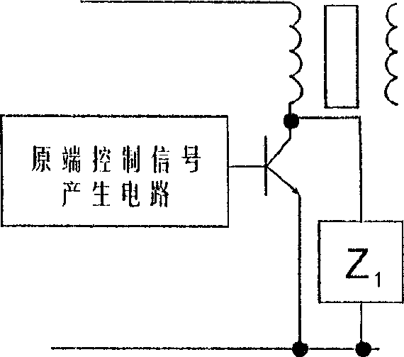
[0029] Such as figure 2 As shown, this embodiment uses a thyristor as a driver, and its original-end control drive device specifically includes a thyristor TR as a driver and a purification and decoupling network Z1 connected in parallel with it. The phase-shift signal of the control signal is added to the control terminal of the thyristor TR, and the thyristor TR generates excitation to the isolation transformer B, which is coupled through the isolation transformer B, and then converted into DC by the rectifier bridge in the rectifier DC control part C. The first capacitor C1 filter and adjustable voltage regulator IC for DC control (it can also be an integrated circuit device with other functions, because the DC load is different, the control purpose is different, and the function of the integrated circuit used is different) and the second control adjustment potentiometer W2 is adjusted, and the second capacitor C2 completes re-filtering and then adds it to the DC load D (a...
Embodiment 2
[0031] The difference with embodiment 1 is: as diagram 2-1 As shown, the bipolar power device (which can be NPN, PNP or compound device) is used as the driver in the original end control drive device.
Embodiment 3
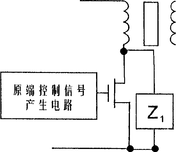
[0033] The difference with embodiment 1 is: as Figure 2-2 As shown, a field effect device (which may be various MOS, BIMOS, VMOS or other field effect devices) is used as a driver in the primary-end control driving device.
[0034] The mechanical actuator of the control is completed by the adjustment box connected to the first control adjustment potentiometer W1. The adjustment box of the present invention adopts a pedal structure, and the components of the original control part A are integrated inside, and the first control of the drive is completed by moving up and down. Adjust potentiometer W1 to rotate (or slide). As shown in Figure 3-1, there is a rubber foot 3 supporting the pedal body under the main body base 1 of the foot pedal. The arc-shaped rack 5 (the teeth are set on the inner side) meshes with the gear 6, and the gear 6 is connected to the adjustment end of the first control adjustment potentiometer W1. When the pedal 2 moves downward, the rack 5 is driven to d...
PUM
 Abstract
Description
Claims
Application Information
 - R&D
- Intellectual Property
- Life Sciences
- Materials
- Tech Scout
- Unparalleled Data Quality
- Higher Quality Content
- 60% Fewer Hallucinations
Browse by: Latest US Patents, China's latest patents, Technical Efficacy Thesaurus, Application Domain, Technology Topic, Popular Technical Reports.
© 2025 PatSnap. All rights reserved.Legal|Privacy policy|Modern Slavery Act Transparency Statement|Sitemap|About US| Contact US: help@patsnap.com