Drum washing machine

一种滚筒洗衣机、洗衣桶的技术,应用在其他洗衣机、洗涤容器、洗涤装置等方向,能够解决移至冷凝导管的外部、洗衣桶不会被均匀地支撑等问题,达到增加方便性的效果

Inactive Publication Date: 2007-01-31
LG ELECTRONICS INC
View PDF0 Cites 15 Cited by
  • Summary
  • Abstract
  • Description
  • Claims
  • Application Information

AI Technical Summary

Problems solved by technology

In this case, many problems arise, including the need to make new molds for the manufacture of laundry tubs
[0015] Second, there is a disadvantage that even if a new mold is made, the washing tub will not be supported evenly, and the connecting parts are moved to the outside of the condensation duct

Method used


Image

  • Drum washing machine
  • Drum washing machine
  • Drum washing machine

Examples


Embodiment Construction

[0035] Reference will now be made in detail to the preferred embodiments of the invention, examples of which are illustrated in the accompanying drawings. Wherever possible, the same reference numbers will be used throughout the drawings to refer to the same or like parts.

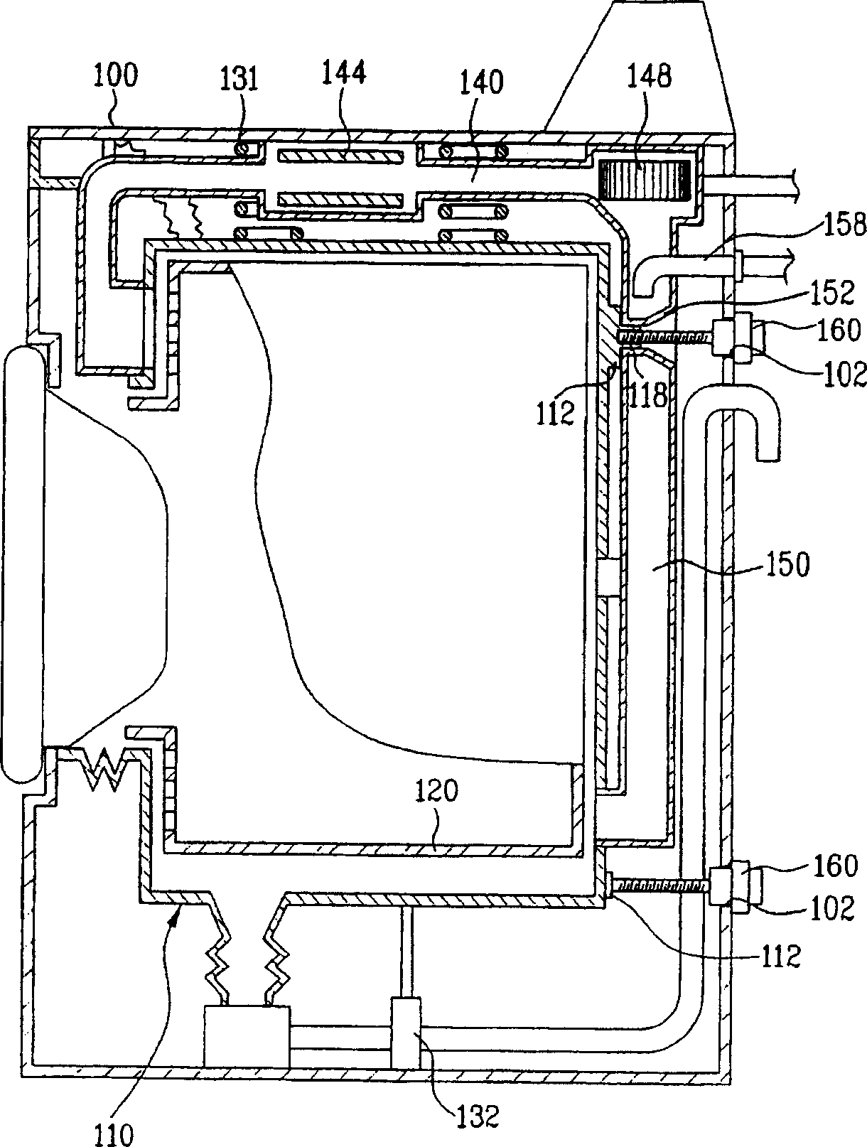
[0036] refer to Figures 3 to 5 , the structure of the drum washing machine of the present invention will be described. Such as Figures 3 to 4 As shown, a washing tub 110 storing washing water is installed in the cabinet 100 , and a drum 120 is rotatably installed inside the drum 110 . A motor (not shown) for transmitting driving force to the drum 120 is installed at a rear side of the tub 100 . The upper end of the washing tub 100 is supported by a plurality of springs 131 suspended on the casing 100 , and the lower end thereof is supported by a plurality of shock absorbers 132 .

[0037] The drying duct 140 is disposed at an upper portion of the washing tub 110 . A fan 148 and a drying heater 144 a...


PUM


Abstract

A drum washing machine having tub coupling structure includes a cabinet having a plurality of coupling holes each receiving a transit bolt on a rear surface thereof, a tub provided in the cabinet so as to store wash water therein and having a plurality of coupling members each coupled with the transit bolt on a rear surface thereof, and a condensing duct provided to be connected with a rear surface of the tub and having a through hole formed at a position corresponding to one of at least three coupling members of the tub so as to be communicated therewith, the through hole to which the transit bolt is inserted.

Description

technical field [0001] The present invention relates to a drum washing machine, in particular to a transportation bolt connection structure of the drum washing machine, so that the washing bucket arranged in the washing machine can be prevented from moving during the transportation of the washing machine. Background technique [0002] Generally, a drum washing machine is a device for washing laundry by rotating a drum with a driving force of a motor when detergent, water, and laundry are put in. The advantage of the drum washing machine is that it prevents clothes from being damaged or entangled, and achieves the effect of friction washing. [0003] A prior art drum washing machine will be described in detail with reference to the drawings. figure 1 A schematic diagram of components of a drum washing machine in the prior art is shown. refer to figure 1 , the drum washing machine includes a casing 1, the front surface of which is provided with a clothes inlet to put in and...

Claims


Application Information

Patent Timeline
Patent Type & Authority Applications(China)
IPC IPC(8): D06F39/00D06F37/22D06F1/00
CPCD06F39/001A45D1/04A45D1/08H05B3/20A45D2200/205D06F37/22Y02B40/00
Inventor 金在汶
Owner LG ELECTRONICS INC
Why Eureka
Try Eureka