


Quick Research
Generate reliable direction feasibility study reports for your R&D in just a few steps.

Technical Q&A
Discover and master advanced knowledge NOW. Basics, ideas, possibilities, all at once.

Find Solutions
As an expert in R&D theories, this can generate solutions to your technical problems instantly.

Evaluate Feasibility
Analyze your overall solution with one click, know your potential R&D risks in advance.

Monitor Landscape
Get weekly tech updates, stay abreast of the latest tech innovations and key insights.
Clamp hook device
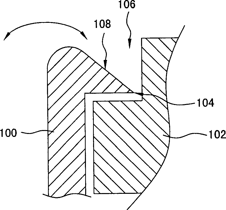
The technology of a hook seat and a hook base is applied in the direction of instruments, casings/cabinets/drawer parts, instrument parts, etc., which can solve the problem of cutting users, affecting convenience, and affecting the appearance of devices And other issues
- Summary
- Abstract
- Description
- Claims
- Application Information
AI Technical Summary
Problems solved by technology
Method used
Image

Examples
Embodiment Construction
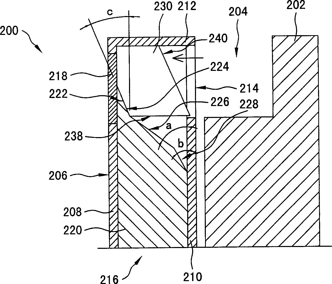
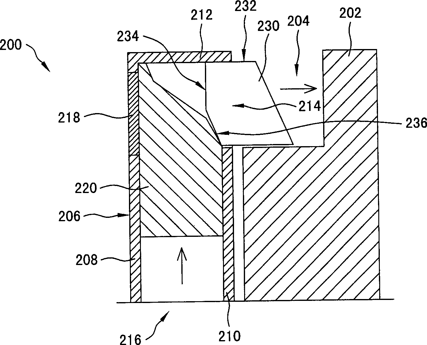
[0011] The invention discloses a hook device, which has a hidden hook, so that the flexibility of the appearance design of the device can be increased, and the convenience and safety of using the hook can be improved. In order to make the description of the present invention more detailed and complete, please refer to figure 2 and image 3 A detailed description of a preferred embodiment of the invention.
[0012] Please refer to figure 2 , which is a schematic diagram illustrating a hook device according to a preferred embodiment of the present invention, wherein the hook is in an original position when not in use. The hook device 200 is mainly composed of a hook base 206 , an adsorption member 218 , a slider 220 , a hook 230 , and a subordinate hook seat 202 . The hook base 206 is mainly composed of a top plate 212 and side walls 210 and 208 opposite to each other, wherein the side walls 210 and side walls 208 are joined to two sides of the top plate 212 to form an acco...
PUM
 Abstract
Description
Claims
Application Information
 - R&D Engineer
- R&D Manager
- IP Professional
- Industry Leading Data Capabilities
- Powerful AI technology
- Patent DNA Extraction
Browse by: Latest US Patents, China's latest patents, Technical Efficacy Thesaurus, Application Domain, Technology Topic, Popular Technical Reports.
© 2024 PatSnap. All rights reserved.Legal|Privacy policy|Modern Slavery Act Transparency Statement|Sitemap|About US| Contact US: help@patsnap.com