
Organic EL element and manufacturing method

A manufacturing method and element technology, applied in the field of organic EL elements and its manufacture, capable of solving problems such as poor conduction of the upper electrode, breakage of the second electrode, breakage of the light-emitting layer, etc., to suppress quality degradation, prevent poor conduction, prevent The effect of process damage

Active Publication Date: 2007-01-31
LG DISPLAY CO LTD
View PDF1 Cites 3 Cited by
  • Summary
  • Abstract
  • Description
  • Claims
  • Application Information

AI Technical Summary

Problems solved by technology

[0008] However, according to the above technique, since the film thickness of the protective film is thick, the luminescent layer and the second electrode are broken due to the level difference or the depression of the protective film, and conduction failure of the upper electrode (cathode electrode) 21 occurs.
That is, a step corresponding to the thickness of the protective film is formed on the side wall of the protective film, or a depression generated by side etching (side etching) when the protective film is formed. The light-emitting layer is broken due to poor steps, or the depression cannot be buried in the light-emitting layer, so there is a problem that the light-emitting layer may break near the depression
Moreover, the second electrode laminated on the light-emitting layer is also likely to break
Therefore, poor conduction of the second electrode and poor operation of the organic EL element itself occur.

Method used


Image

  • Organic EL element and manufacturing method
  • Organic EL element and manufacturing method
  • Organic EL element and manufacturing method

Examples


no. 1 approach

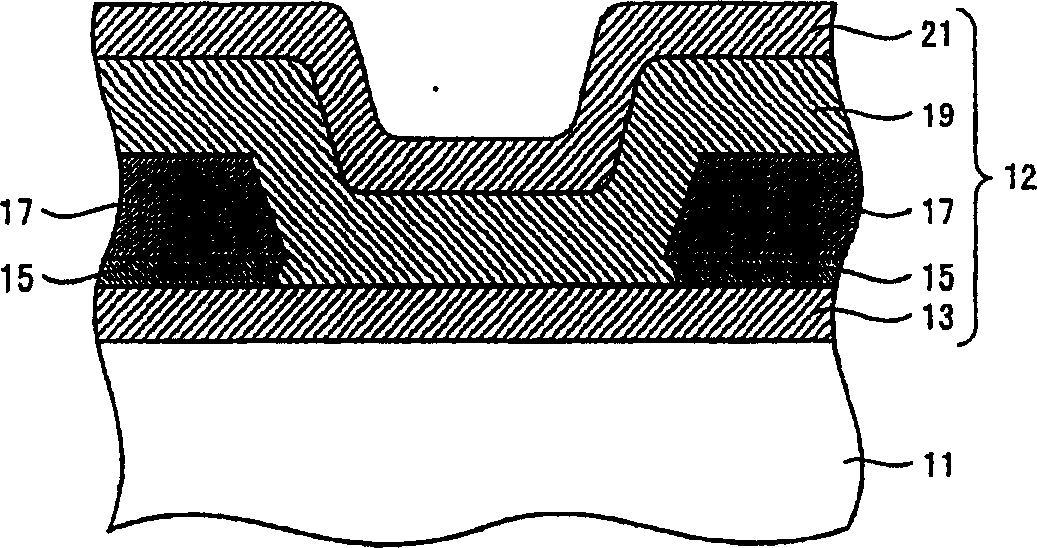
[0045] figure 1 It is a cross-sectional view showing a schematic structure of the organic EL element according to the first embodiment of the present invention. Such as figure 1 As shown, the organic EL element of the present embodiment is constituted to include: a base portion 11 on which driving elements such as TFTs and wiring for driving the organic EL element are formed on a base such as a glass substrate; The element portion 12 is formed with an organic EL element. Furthermore, the organic EL element of this embodiment adopts a top emission type (top emission) structure in which light is taken in from the upper surface side (the side of the organic electroluminescent element portion 12 ). In addition, although the planarization layer for planarizing the upper layer such as the above-mentioned TFTs and wirings is provided on the base part 11, since it is not directly related to the gist of the present invention, detailed description and illustration are omitted here.

...

no. 2 approach

[0083] Figure 10 It is a cross-sectional view showing the structure of the organic EL element according to the second embodiment of the present invention. Here, the description will mainly be given to structures different from those of the organic EL element of the first embodiment, and the description of other common structures will be omitted in principle.

[0084] In this embodiment, unlike the first embodiment, the protective material layer 15a in the opening of the interlayer insulating layer 17 is not completely removed, but a part of the protective material layer 15a in the opening of the interlayer insulating layer 17 remains. , thereby forming the concave portion 15 b in the protective layer 15 . As a result, the film thickness of protective layer 15 in the inner region of the opening of interlayer insulating layer 17 is set smaller than the film thickness of protective layer 15 in the outer region of the opening of interlayer insulating layer 17 .

[0085] By adop...


PUM


Abstract

A high quality organic EL element preventing the quality degradation and poor conduction caused by the electrode processing damage and a manufacturing method with the same are provided. The organic EL element comprises: a first electrode (13); a protective layer (15) formed on the first electrode (13) with an opening for uncovering the same; an insulation layer (17) on the protective layer (15); an organic layer (19) comprising a light-emitting layer on the region starting from the insulation layer (17) and till the uncased first electrode (13); and a second electrode (21) formed on the organic layer (19), wherein the film of the organic layer (19) is thicker than the one of the protective layer.

Description

technical field [0001] The present invention relates to an organic EL element and its manufacturing method. Background technique [0002] An organic electroluminescence element (organic electroluminescence (EL) element) is an element that excites and emits light by applying an electric field to an organic fluorescent compound. Such organic EL elements have characteristics such as self-luminescence, wide viewing angle, high response speed, low driving voltage, and full color. They are currently being put into practical use and can be applied to small displays, panels, outdoor screens, computers, and televisions. Color flat panel display components such as screens, etc. [0003] The organic EL element has a structure in which an organic layer having light-emitting properties is sandwiched between two electrodes. When a DC voltage is applied to both electrodes, holes are injected into the organic layer from the anode, and electrons are injected into the organic layer from the...

Claims


Application Information

Patent Timeline
Patent Type & Authority Applications(China)
IPC IPC(8): H01L51/50H01L51/56
Inventor 加纳圭吾师冈光雄莲见太朗福冈宏美渡边雅也
Owner LG DISPLAY CO LTD
Learn More