
Motor controller

A control device and motor technology, applied in motor generator control, AC motor control, electronic commutation motor control, etc., can solve the deterioration of estimation accuracy, difficulty in improving magnetic pole position accuracy, friction fluctuation, stable disturbance load reliability reduction, etc. question

Inactive Publication Date: 2007-01-24
MITSUBISHI ELECTRIC CORP
View PDF2 Cites 14 Cited by
  • Summary
  • Abstract
  • Description
  • Claims
  • Application Information

AI Technical Summary

Problems solved by technology

[0009] In the initial magnetic pole position estimating device described in Patent Document 1, the initial magnetic pole position estimating formula is used to accurately estimate the declination angle of the initial magnetic pole position that exists when the encoder is mounted on the AC synchronous motor, and by displaying it, It has the effect of correctly adjusting the initial magnetic pole position, but because it is only in the command torque current (q-axis current command iqc * ) = 0, it can be estimated, so there is a problem that it cannot be estimated in normal operations such as speed control
[0010] In addition, in the initial magnetic pole position estimating device in the above-mentioned Patent Document 1, after displaying the shaft deflection angle and reinstalling the encoder, a series of operations of re-estimating the shaft deflection angle must be repeated, and there is a problem of invalid operation.
[0011] In addition, in the initial magnetic pole position estimating device in the above-mentioned Patent Document 1, since a division method is used in estimating the shaft deflection angle, there is a problem that the reliability against noise, frictional fluctuations, stable disturbance loads, etc. is lowered.
[0012] In addition, in the initial magnetic pole position estimating device in the above-mentioned Patent Document 1, constants such as an inertia value and friction are required for estimating the shaft deflection angle, so there are cases where the correct constants cannot be obtained, and the estimation accuracy is high. Amplitude deterioration problem
[0013] In addition, the motor control device in the above-mentioned Patent Document 2 can estimate the magnetic pole position of the synchronous motor by a simple method by detecting the current flowing through the other orthogonal axis with a predetermined phase using the signal for estimation, and performing multiplication. However, since the structure does not include a speed detector or a position detector, the speed feedback information cannot be used, so the actual speed change or position change cannot be detected, so there is a problem that it is difficult to improve the accuracy of the magnetic pole position estimation
[0014] In addition, in the motor control device in Patent Document 2, since electrical saliency is used, there is a problem that it is difficult to detect in a motor without electrical saliency or a small motor.
[0015] In addition, in the motor control device in the above-mentioned Patent Document 2, because of the characteristic of being electrically closed, only current feedback can be used (current command cannot be used), so there is a problem of being affected by current detection noise.
[0016] In addition, in the motor control device described in Patent Document 2, since the superimposed signal and the detection signal are not in the same phase, it is necessary to perform detection with a specific phase timing, or to calculate the peak value and the rate of change, etc. , there is a problem that the instruction program becomes complicated

Method used


Image

  • Motor controller
  • Motor controller
  • Motor controller

Examples


Embodiment approach 1

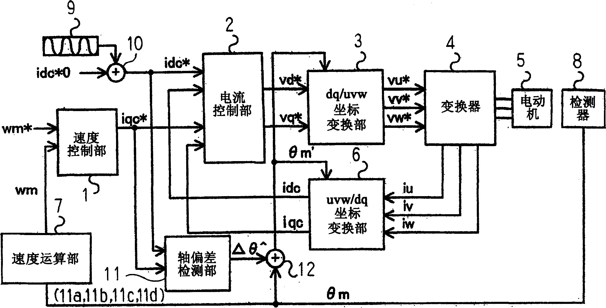
[0042] figure 1 It is a figure which shows the structure of the motor control apparatus concerning Embodiment 1 of this invention. also, figure 2 It is a figure which shows an example of the structure of the shaft deviation detection part in the motor control apparatus concerning Embodiment 1 of this invention. In addition, FIG. 3 is a diagram illustrating the relationship between the dq axis (dm-qm axis) of the actual motor and the dq axis (dc-qc axis) of the control.

[0043] use figure 1 ˜ FIG. 3 , the processing operation of the motor control device according to Embodiment 1 will be described.

[0044] exist figure 1 , the speed control unit 1 inputs the speed command wm * and the actual speed wm, follow the speed command wm with the actual speed wm * The way, using PI control, etc., for speed control, output q-axis current command iqc * . In addition, the current control unit 2 inputs the d-axis current command idc * , q-axis current command iqc * , d-axis curr...

Embodiment approach 2

[0078] Next, use Figure 4 Next, the processing operation of the shaft deviation detection unit 11b in the motor control device according to the second embodiment will be described. exist Figure 4 Among them, 101, 102, 104, 105 and figure 2 The same, and its description is omitted. Figure 4 The structure of the axis misalignment detection unit 11b shown is that in figure 2 Between the input filters 101, 102 and the adaptive input calculation unit 103a in the axis deviation detecting unit 11a shown, a sign detector 106 as a first sign detector and a sign detector 107 as a second sign detector are inserted. .

[0079] The d-axis signal idh for axis deviation detection and the q-axis signal iqh for axis deviation detection after filter processing by the input filters 101 and 102 are input, and the signs are detected by the sign detectors 106 and 107 as signed axis deviation detection d The axis signal sign(idh) and the signed q-axis signal sign(iqh) for axis deviation de...

Embodiment approach 3

[0085] Next, use Figure 5 The processing operation of the shaft deviation detection unit 11c in the motor control device according to Embodiment 3 will be described.

[0086] Using the input filters 101 and 102, the d-axis current command idc of the input shaft deviation detection unit 11c * and q-axis current command iqc * (or torque current error iqm) is filtered, and the d-axis signal idh for shaft deviation detection and the q-axis signal iqh for shaft deviation detection are output.

[0087] The estimated output computing unit 108 multiplies the shaft deviation detection d-axis signal idh filtered by the input filter 101 by an output shaft deflection estimated value Δθ^ to be described later, and outputs an estimated output (idh×Δθ^). In addition, the axis deviation error calculation unit 109 acquires the difference between the axis deviation detection q-axis signal iqh filtered by the input filter 102 and the estimated output (idh×Δθ^) output from the estimated output...


PUM


Abstract

A motor controller wherein a superimposition signal generating section outputs a superimposition signal idh of repetitive waveform such as a triangular wave or a sine wave during motor speed control, a d-axis current command generating section adds the superimposition signal idh to a d-axis current command idc*0 to output a d-axis current command idc*, an axis offset detection section receives the d-axis current command idc* and a q-axis current command iqc* to output an axis offset angle estimate deltatheta', an axis offset correction section receives the axis offset angle estimate deltatheta' and an actually detected position thetam to output a corrected position thetam'. The axis offset can be detected and corrected by computation at a given time in real time during normal operation.

Description

technical field [0001] The present invention relates to a motor control device for controlling a synchronous motor, and more particularly, to a motor control device having a shaft deviation detection unit that detects the distance between a dq axis of a synchronous motor that is a control object and a controlled dq axis. Axis angle. Background technique [0002] As the servo control of synchronous motors, vector control is generally performed. Vector control is a control method that divides the current into the direction of the magnetic field flux of the motor (d-axis) and the direction (q-axis) orthogonal to it, and performs current control respectively. In this vector control, in order to efficiently generate torque, it is necessary to detect the position of the magnetic poles. [0003] In addition, linear motors are often used in combination with incremental encoders that cannot detect the absolute position of the motor when the power is turned on. However, since increme...

Claims


Application Information

Patent Timeline
Patent Type & Authority Applications(China)
IPC IPC(8): H02P21/00H02P6/18H02P6/06H02P6/08H02P6/17H02P6/182H02P6/28H02P21/06H02P21/18H02P21/22H02P21/24H02P21/34H02P23/14H02P23/16H02P25/026H02P27/04
CPCH02P21/06H02P21/0003
Inventor 寺田启长野铁明原田保信高桥和孝
Owner MITSUBISHI ELECTRIC CORP
Learn More