Door closer with a drive

A technology of driving device and closing device, which is applied in the direction of switches with braking devices, wing parts, manufacturing tools, etc. It can solve the problems that the long-extended groove of the shell cannot be provided and it is difficult to install, so as to achieve good sealing , the effect of quick replacement

Inactive Publication Date: 2007-01-24
DORMA GMBH & CO KG
View PDF2 Cites 4 Cited by
  • Summary
  • Abstract
  • Description
  • Claims
  • Application Information

AI Technical Summary

Problems solved by technology

However, such housing shapes are in many cases difficult to install, since elongated slots for the housing are generally not possible in the floor area

Method used


Image

  • Door closer with a drive
  • Door closer with a drive
  • Door closer with a drive

Examples


Embodiment Construction

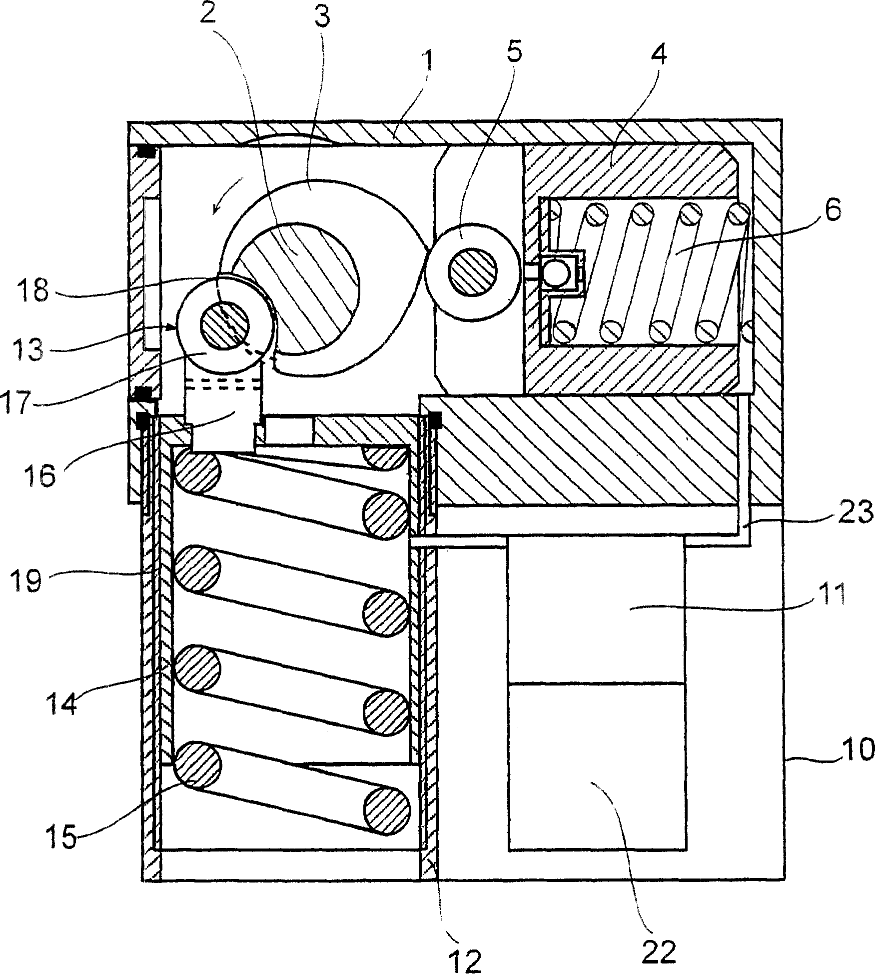
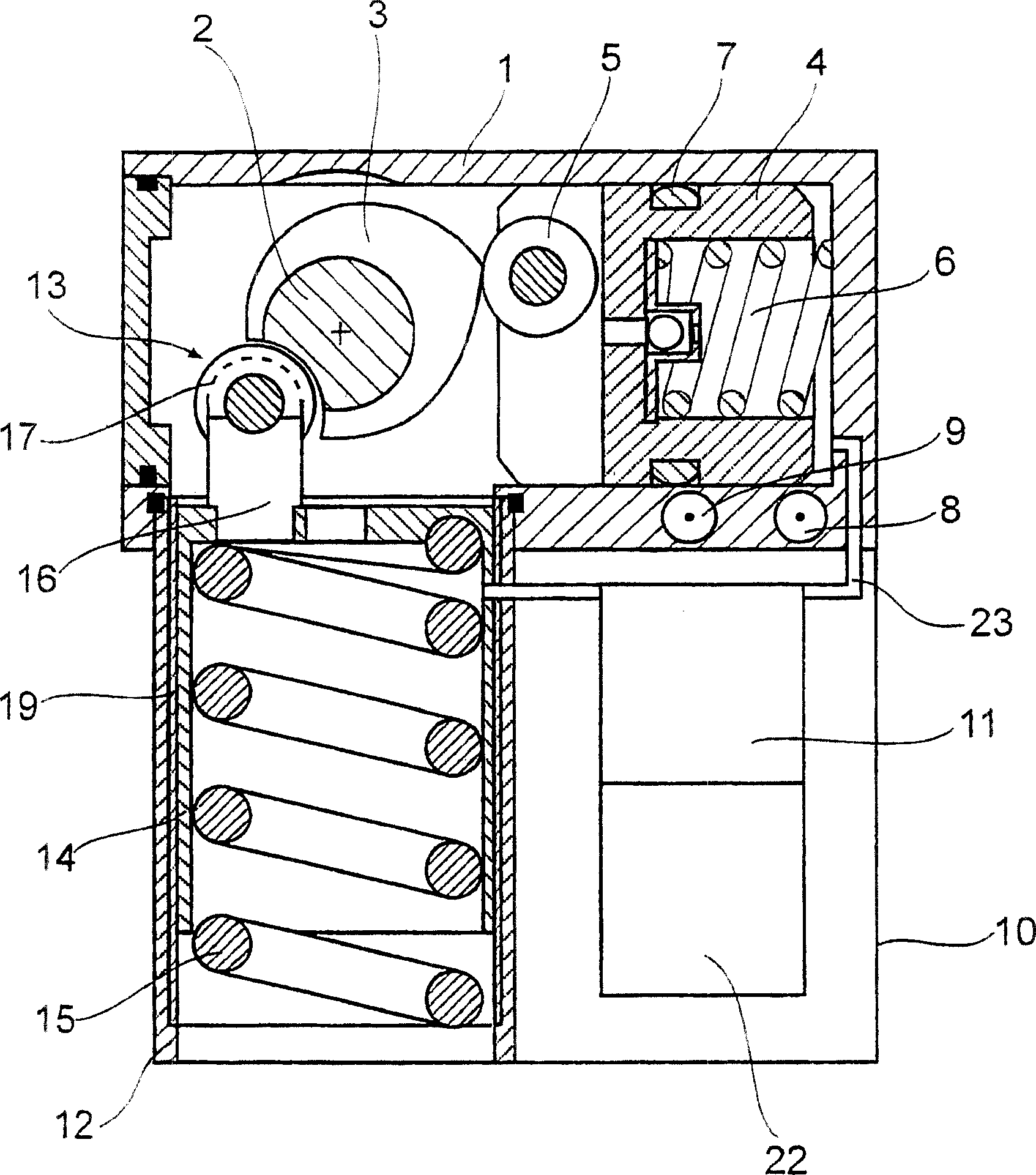
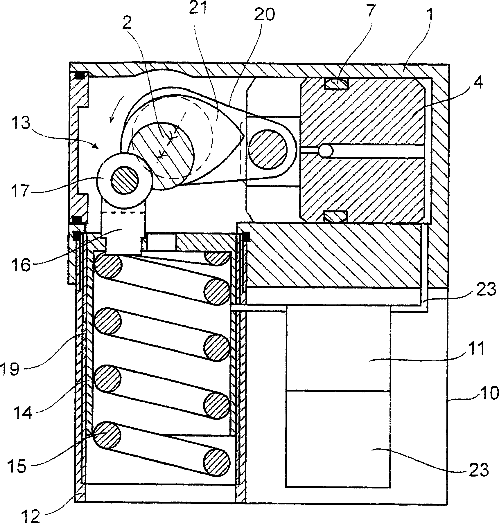
[0027] Figures 1 to 3 The door closer according to the invention has only been described in terms of the relevant aspects of the invention.

[0028] The door closer according to the invention has a substantially rectangular housing 1 in which a shaft 2 which can be connected to a door leaf or the like is mounted. The shaft 2 has an eccentric disk 3 which is held in engagement with a roller 5 bearing on a brake piston 4 . The brake piston 4 is in turn mounted longitudinally displaceably in the housing 1 , wherein the brake piston is urged in the direction of the shaft 2 by a spring 6 which is likewise mounted in the housing 1 .

[0029] A seal 7 is arranged in an annular groove on the brake piston 4 , which seal rests on the wall of the housing 1 . At the end of the housing 1 remote from the shaft 2 there is a regulating valve 8 with which the movement of the brake piston 4 can be influenced by regulating the flow of brake fluid in the housing 1 . In this way, for example, ...


PUM


Abstract

A door closer includes a housing; a shaft supported in the housing and connectable to a door; a brake piston supported in the housing and charging the shaft, the brake piston and the housing defining a first space away from the shaft; a blocking member; a spring loading the blocking member and extending orthogonally from the housing; and a pump for pumping brake fluid to or from the first space. The pump is disposed in a second space formed between the housing and the spring. The shaft is lockable in a position by the blocking member.

Description

technical field [0001] The invention relates to a door closer with an electrohydraulic / electromechanical drive and a housing in which a shaft for connection to a door leaf or the like is supported, wherein the shaft is controlled by A spring-loaded locking element can be locked in at least one position. Background technique [0002] Such door closers are well known. Such leaf closers usually have a housing in which a shaft connectable to a leaf or the like, a spring-loaded locking element and a brake piston are arranged. The locking element and the brake piston are essentially connected in series on opposite sides of the shaft in such a way that an elongated housing shape is formed overall. However, housing shapes of this type are in many cases difficult to install, since generally no elongated slots for the housing can be provided in the floor area. Such a door closer is known from DE 40 38 720 C2 as an upper door closer, and from DE 27 55 787 A1 as a floor spring. Con...

Claims


Application Information

Patent Timeline
Patent Type & Authority Applications(China)
IPC IPC(8): E05F3/04E05F3/22E05F15/12E05F3/10
CPCE05F3/223E05F3/104E05F15/12E05Y2900/132E05F3/04E05F15/611
Inventor L·金策尔V·比内克
Owner DORMA GMBH & CO KG
Why Eureka
Try Eureka