
Multi-mode image processing

A technology of alpha and alpha value, which is applied in the field of encoding and decoding images, can solve the problem of not being able to deal with alpha, and achieve the effect of simple hardware implementation

Active Publication Date: 2007-01-17
TELEFON AB LM ERICSSON (PUBL)
View PDF1 Cites 10 Cited by
  • Summary
  • Abstract
  • Description
  • Claims
  • Application Information

AI Technical Summary

Problems solved by technology

The fact that S3TC cannot handle more accurate alphas is one of the main drawbacks of the system

Method used


Image

  • Multi-mode image processing
  • Multi-mode image processing
  • Multi-mode image processing

Examples


Embodiment Construction

[0057] Throughout the drawings, the same reference characters are used for corresponding or identical parts.

[0058] The present invention relates to image and graphics processing, and in particular to encoding or compressing alpha images and decoding or decompressing encoded (compressed) alpha images.

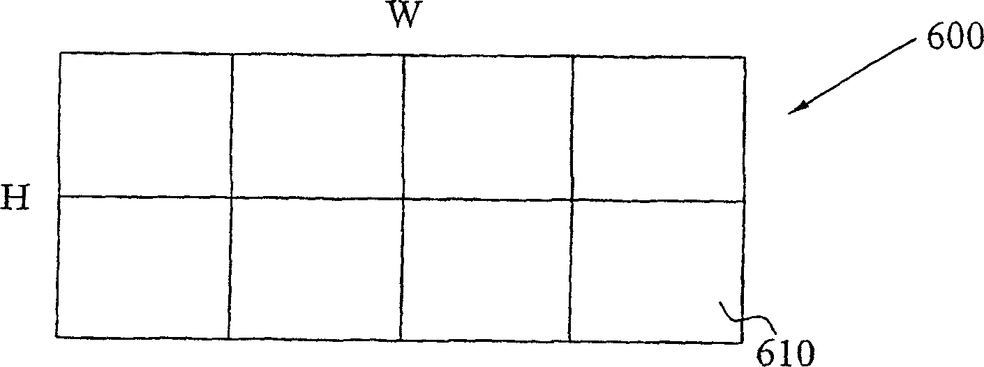
[0059] Generally, according to the invention, during image encoding, an alpha image is decomposed or partitioned into a plurality of image blocks. Each such image block then contains a plurality, ie at least two image elements, which have image element-related properties, in particular a certain color and an associated alpha or transparency value. The image blocks are then encoded or compressed to generate an encoded representation of the image.

[0060] When the encoded image is to be displayed on the screen, or when geometric primitives associated with the encoded image are to be rendered, the relevant image elements of the encoded image block are identified and decoded. ...


PUM


Abstract

In an image-encoding scheme, an input image is decomposed into several image blocks (600) comprising multiple image elements (610), e.g. pixels or texels. The image blocks (600) are then encoded into encoded block representations (700). Such a block representation (700) comprises a color codeword (710), an intensity codeword (720) and a sequence (730) of intensity representations. The color codeword (710) is a representation of the colors of the image elements (610) of the block (600). The intensity codeword (720) is a representation of a set of multiple intensity modifiers for modifying the intensity of the image elements (610) in the block (600). The representation sequence (730) includes an intensity representation for each image element (610) in the block (600), where a representation identifies one of intensity modifiers in the intensity modifier set. During decoding, the color and intensity codewords (710, 720) and intensity representations (730) are used to generate a decoded representation of the image elements (610) in the block (600).

Description

technical field [0001] The present invention relates generally to image processing, and in particular to methods and systems for encoding and decoding images. Background of the invention [0002] The presentation and reproduction of images and graphics on data processing systems and user terminals such as computers and especially on mobile terminals has greatly improved in recent years. For example, three-dimensional (3D) graphics and images have many compelling applications on such terminals, including gaming, 3D maps and messaging, screen savers, and human-machine interfaces. [0003] The 3D graphics rendering process typically includes three sub-phases. In short, the first phase, the application phase, creates several triangles. In the second stage, the geometry stage, the corners of these triangles are transformed, projected and lit. In the third stage, the rasterization stage, images, usually represented as textures, can be glued to the triangles, increasing the real...

Claims


Application Information

Patent Timeline
IPC IPC(8): G06T9/00H04N7/30H04N7/26
CPCH04N7/26957H04N19/00278G06T9/00H04N19/00315H04N7/26287H04N19/00309H04N7/26244H04N7/26148H04N19/00981H04N19/00024H04N7/26015H04N19/105H04N19/176H04N19/184H04N19/186H04N19/98
Inventor J·斯特罗姆
Owner TELEFON AB LM ERICSSON (PUBL)
Learn More