Scroll fluid machinery

A technology of fluid machinery and scroll, applied in the countermeasure field of capacity control, which can solve the problems of narrow control range and low efficiency, and achieve the effect of reducing the number of parts and suppressing the decline of compression ratio

Inactive Publication Date: 2007-01-17
DAIKIN IND LTD
View PDF1 Cites 10 Cited by
  • Summary
  • Abstract
  • Description
  • Claims
  • Application Information

AI Technical Summary

Problems solved by technology

[0006] [0005] However, in the scroll compressor shown in the conventional patent document 1, because the piston valve mechanism is used, the capacity can only be adjusted to two stages (two stages), and the control range is narrow. question
In addition, there is a problem that the power required to operate the above-mentioned piston valve mechanism reduces the efficiency.

Method used


Image

  • Scroll fluid machinery
  • Scroll fluid machinery
  • Scroll fluid machinery

Examples


Embodiment Construction

[0056] [0043] Hereinafter, embodiments of the present invention will be described in detail with reference to the accompanying drawings.

[0057] [0044] (the first embodiment of the invention)

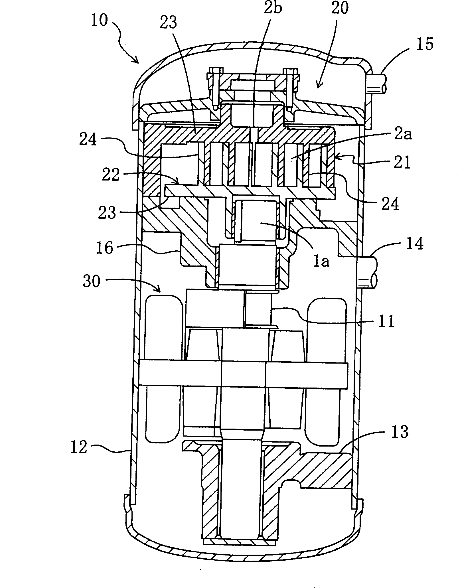
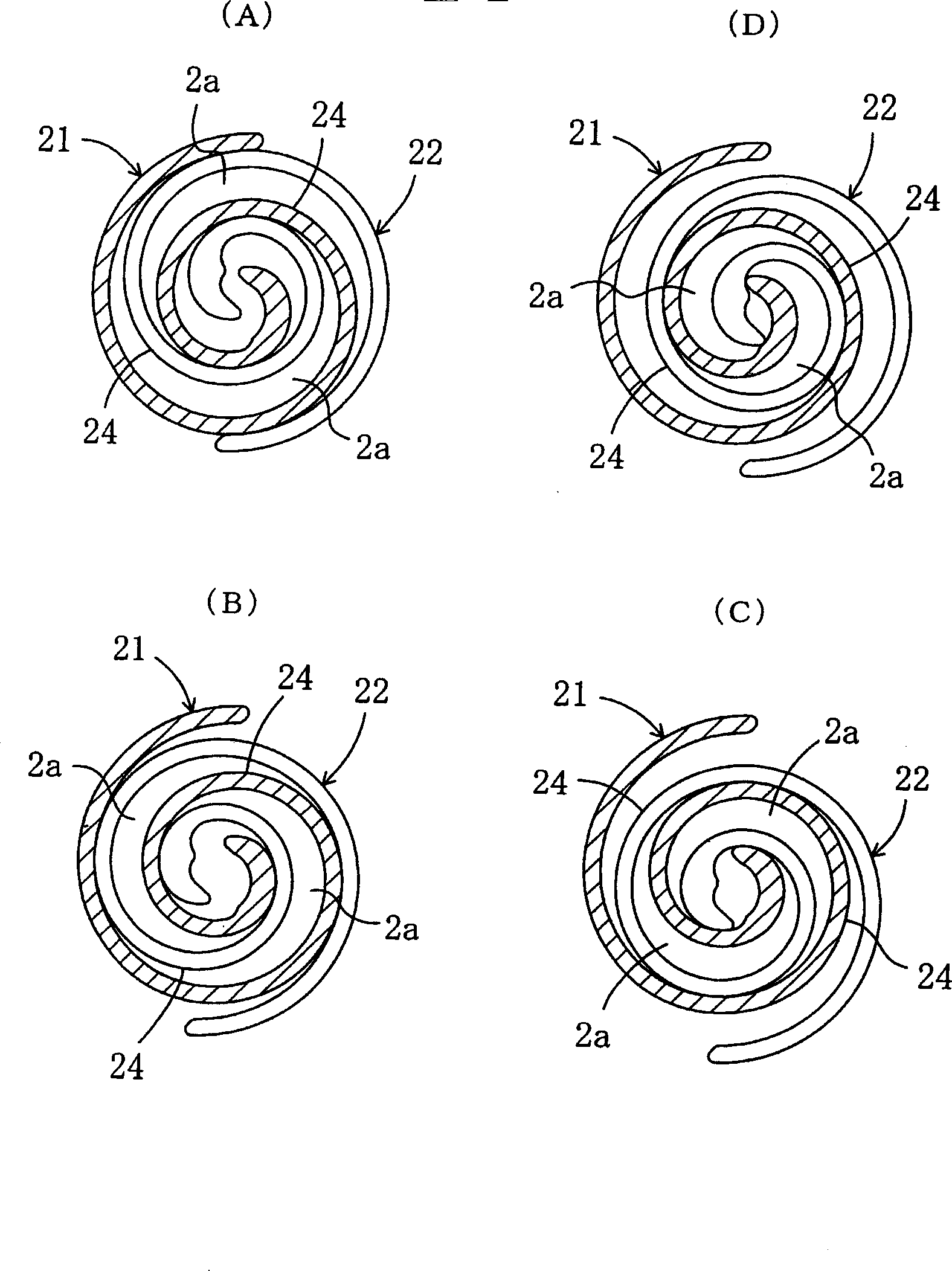
[0058] Such as figure 1 and figure 2 As shown, the scroll fluid machine of this embodiment is constituted by a scroll compressor 10 . The scroll compressor 10 includes a compression mechanism 20 , a motor 30 and a drive shaft 11 . Furthermore, the above-mentioned scroll compressor 10 is installed in a refrigerant circuit such as an air conditioner to compress refrigerant gas.

[0059] [0045] The motor 30 is connected to the compression mechanism 20 through the drive shaft 11. The compression mechanism 20 and the motor 30 are accommodated in the cylindrical casing 12 in a sealed state. The above-mentioned scroll compressor 10 is a vertical type, a compression mechanism 20 is arranged above the casing 12, a lower bearing 13 is arranged below the casing 12, and a motor is arranged ...


PUM


Abstract

The invention discloses a scroll fluid machinery, wherein a fixed scroll (21) with a scroll-shaped lap (24) and a movable scroll (22) are installed on an end plate (23). High polymer actuators (40) adjusting a clearance between the lap (24) and the end plate (23) are fitted into recessed parts at the tip of the lap (24). The high polymer actuators (40) change its shape in the height direction of the lap (24) to adjust the clearance. The high polymer actuators (40) are commonly used as seal members between the end plate (23) and the lap (24). On the other hand, the recessed parts are formed so that a thickness between the recessed parts and the inner peripheral surface of the lap (24) is different from a thickness between the recessed parts and the outer peripheral surface of the lap (24).

Description

technical field [0001] [0001] The present invention relates to a scroll fluid machine, and particularly relates to a measure for controlling capacity. Background technique [0002] [0002] Conventionally, a scroll compressor is installed in an air conditioner or the like. Since the compression ratio of the scroll compressor is constant, an electric adjustment circuit such as an inverter is installed to control the number of revolutions and control the capacity. [0003] [0003] However, if the above-mentioned electrical adjustment circuit is provided, there is a problem that a considerable cost is required for the electrical adjustment circuit. Furthermore, in the above-mentioned electrical adjustment circuit, there is also a problem that the power consumption is large and the efficiency is lowered due to the electrical loss of the inverter or the like. [0004] [0004] Then, as shown in Patent Document 1, there is a device that forms a bypass circuit on the fixed scroll and ...

Claims


Application Information

Patent Timeline
Patent Type & Authority Applications(China)
IPC IPC(8): F04C18/02F04C18/08F04C27/00F04C28/26
CPCF04C28/265F05C2251/08F04C18/084F04C18/0284F04C27/005
Inventor 增田正典东洋文鉾谷克己
Owner DAIKIN IND LTD
Why Eureka
Try Eureka