2-dimensional image display device
A technology for display devices and two-dimensional images, applied in projection devices, optics, instruments, etc., to achieve simple production, reduce speckle noise, improve quietness and durability
- Summary
- Abstract
- Description
- Claims
- Application Information
AI Technical Summary
Problems solved by technology
Method used
Image
Examples
Embodiment approach 1
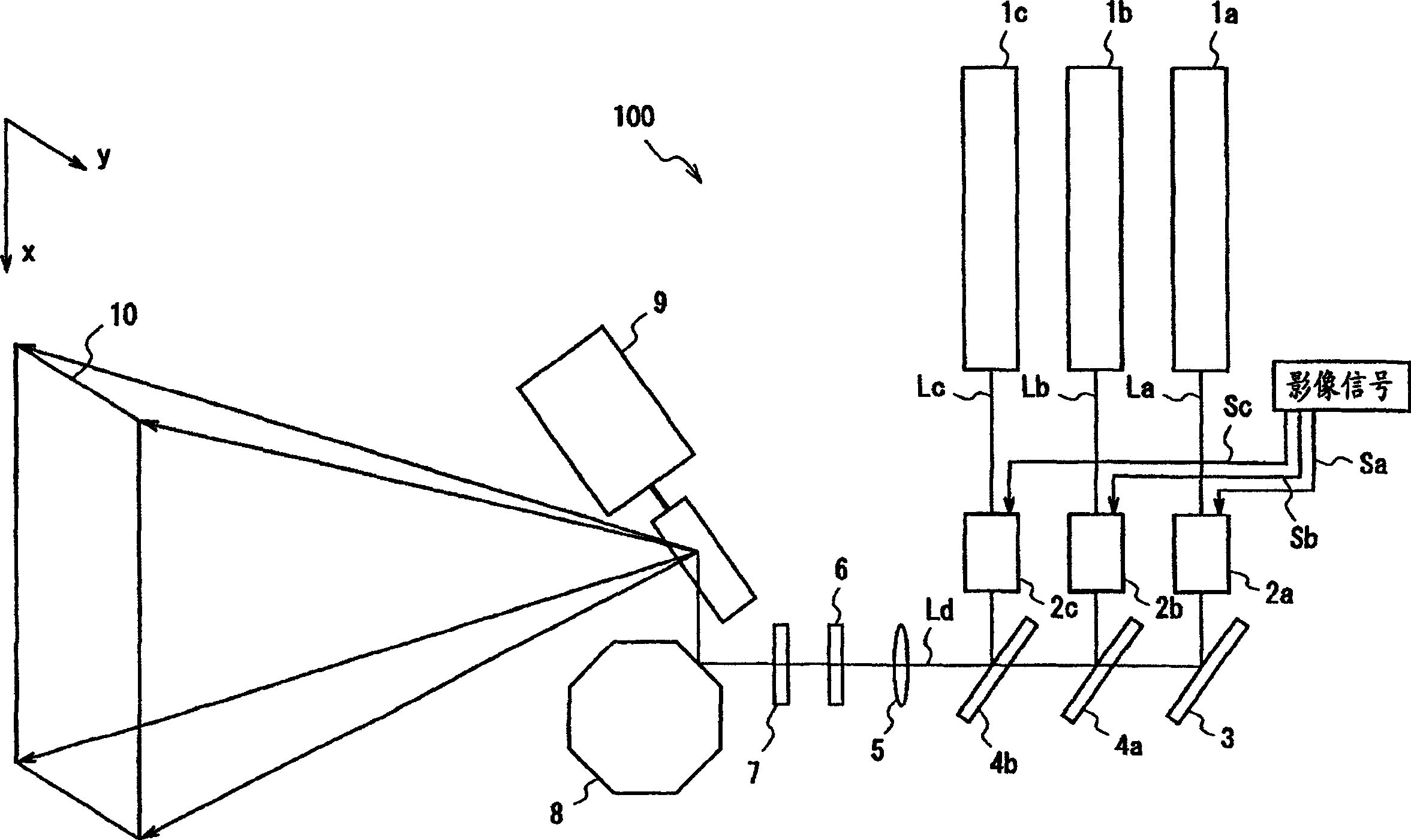
[0095] figure 1 is a diagram showing a schematic configuration of a two-dimensional image display device according to Embodiment 1 of the present invention.
[0096] figure 1 The illustrated two-dimensional image display device 100 includes: laser light sources 1a-1c corresponding to the three colors of RGB, and laser light sources La-Lc output from the laser light sources 1a-1c whose intensity is modulated according to the primary color signals Sa-Sc of the input image signal. light modulators 2a-2c. Among them, laser light sources 1a, 1b, 1c can use gas lasers such as He-Ne lasers, He-Cd lasers, Ar lasers, semiconductor lasers of AlGaInP type and GaN type, and SHG (second harmonic wave generation) lasers, etc.
[0097] In addition, the laser display 100 has a mirror 3 that reflects the laser light La modulated by the light modulator 2a, and a dichroic mirror 4a that synthesizes the laser light La reflected by the mirror 3 and the laser light Lb modulated by the light modu...
Embodiment approach 2
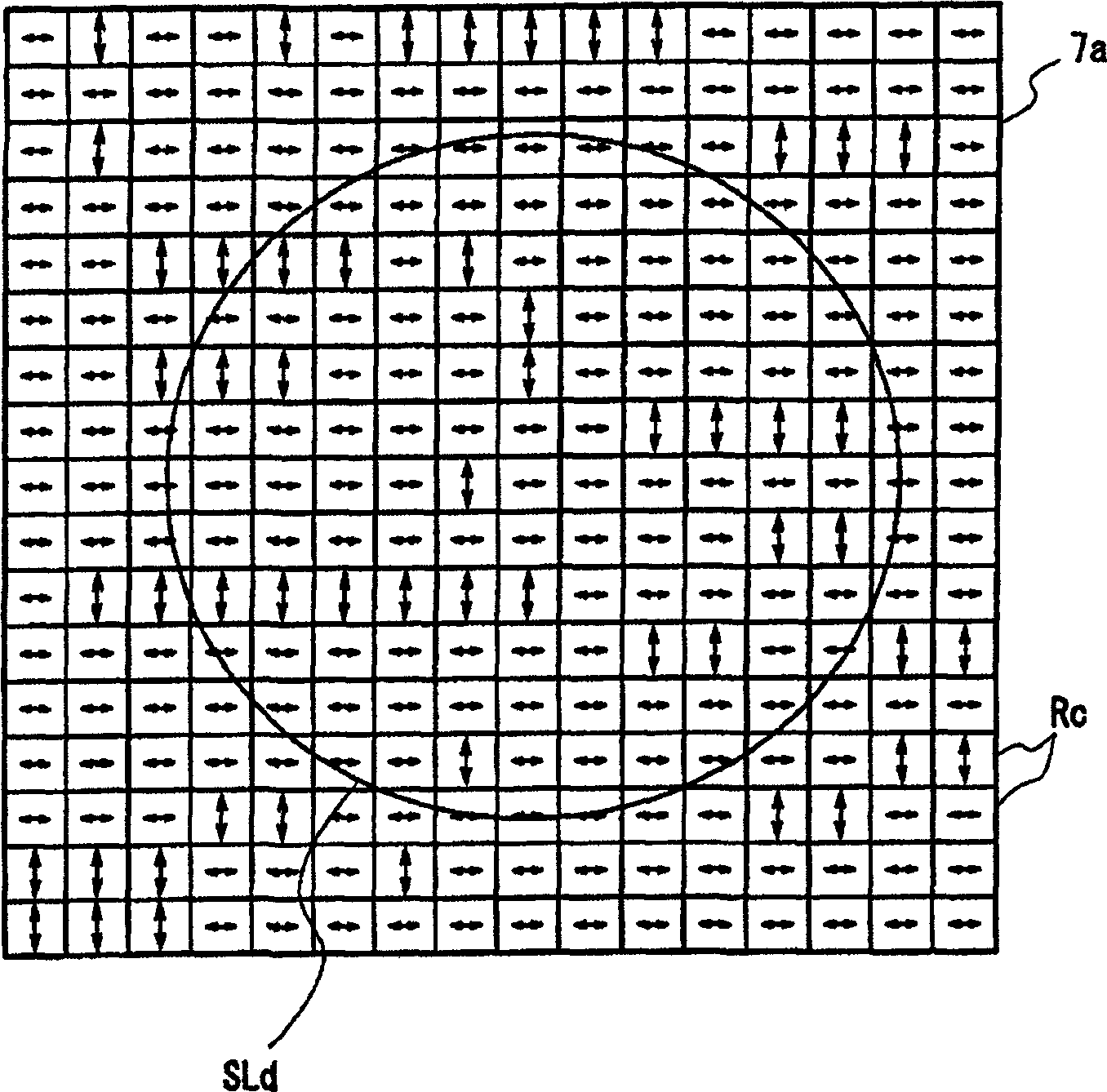
[0132] 5(a) and 5(b) are diagrams illustrating a two-dimensional image display device according to Embodiment 2 of the present invention. Fig. 5(a) is a plan view showing a birefringent diffusion sheet 7c constituting the two-dimensional image display device. 5( b ) shows the cross-sectional structure of the birefringent diffuser 7c, and schematically shows the phase distribution of the illumination light incident on the birefringent diffuser 7c and the illumination light emitted from the birefringent diffuser 7 .
[0133] In the two-dimensional image display device of the second embodiment, the birefringent diffusion sheet 7c in which the substrate thickness of the material having birefringence is randomly changed in space is used instead of the birefringent diffusion sheet 7 of the two-dimensional image display device 100 of the first embodiment. . Therefore, other configurations of this second embodiment are the same as those of the first embodiment.
[0134] The birefrin...
Embodiment approach 3
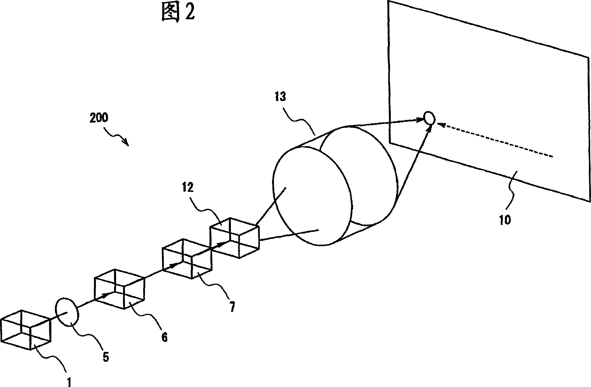
[0147] Figure 7 In order to explain the diagram of the two-dimensional image display device according to Embodiment 3 of the present invention, a speckle noise canceling optical system in the two-dimensional image display device is schematically shown.
[0148] The two-dimensional image display device according to the third embodiment is a device in which the polarization state modulator 6 and the birefringent diffusion sheet 7 c constituting the speckle noise canceling optical system according to the second embodiment are integrated. In addition, other configurations of the third embodiment are the same as those of the second embodiment.
[0149] The speckle noise cancellation optical system of the two-dimensional image display device according to Embodiment 3 is made of a single LiNbO 3 A system in which a polarization state modulator 6e for modulating the polarization state of the laser light Ld and a birefringent diffuser 7e for spatially changing the phase of the polari...
PUM
| Property | Measurement | Unit |
|---|---|---|
| wavelength | aaaaa | aaaaa |
Abstract
Description
Claims
Application Information
 - R&D
- Intellectual Property
- Life Sciences
- Materials
- Tech Scout
- Unparalleled Data Quality
- Higher Quality Content
- 60% Fewer Hallucinations
Browse by: Latest US Patents, China's latest patents, Technical Efficacy Thesaurus, Application Domain, Technology Topic, Popular Technical Reports.
© 2025 PatSnap. All rights reserved.Legal|Privacy policy|Modern Slavery Act Transparency Statement|Sitemap|About US| Contact US: help@patsnap.com


