Valve

A technology of valves and valve bodies, applied in valve details, diaphragm valves, valve devices, etc., can solve problems such as liquid leakage, deterioration of yield, and inconsistent time, so as to achieve stable liquid flow, reduce deterioration of yield, and make it difficult for bubbles to stay Effect

Inactive Publication Date: 2007-01-10
ASAHI YUKIZAI KOGYO CO LTD
View PDF2 Cites 12 Cited by
  • Summary
  • Abstract
  • Description
  • Claims
  • Application Information

AI Technical Summary

Problems solved by technology

[0003] In the conventional suck-back valve integrated with the on-off valve, since the on-off valve and the suck-back valve are controlled independently, there is the following problem: The timing is consistent, and the specified suction volume cannot be obtained, which will cause liquid leakage
In addition, it takes time to adjust the time, and there is also the following problem: even after the adjustment has been completed, if the air pressure for the valve action changes, the closing of the on-off valve and the timing of the suction action will not coincide, so it is necessary to make frequent adjustments
Furthermore, in the case of applications such as application of photoresist liquid in semiconductor manufacturing, since the on-off valve using the diaphragm has a structure in which air bubbles tend to stagnate inside the valve chamber, there will be the following problems: stagnation Air bubbles flow out and spread to the wafer, resulting in uneven coating and deterioration of yield
Also, the same problem applies to suckback valves that use diaphragms

Method used


Image

  • Valve
  • Valve
  • Valve

Examples


Embodiment Construction

[0030] Embodiments of the present invention will be described below with reference to the drawings, but it goes without saying that the present invention is not limited to the embodiments.

[0031] For the first embodiment of the present invention in Figure 1 to Figure 7 Indicated.

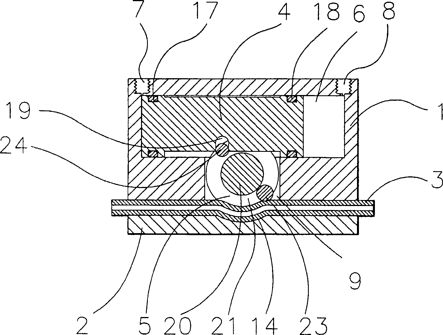
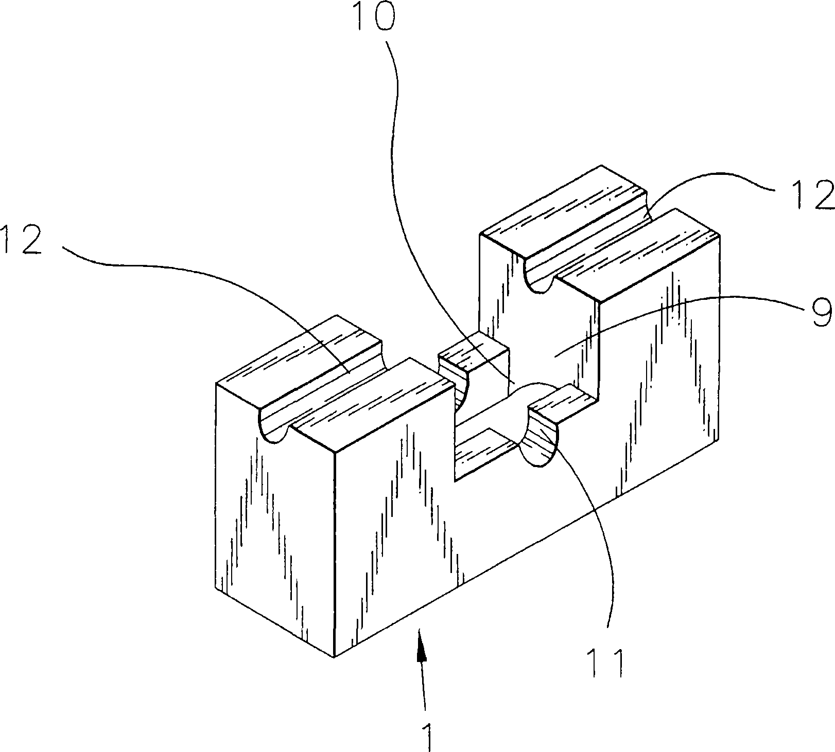
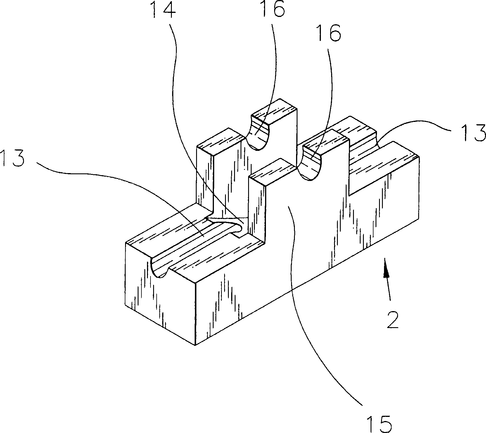
[0032] exist figure 1 Among them, the reference numeral "1" refers to the upper side valve box. The upper side valve box 1 has a cylinder chamber 6 and a pair of working fluid supply ports 7, 8 communicating with the cylinder chamber 6 inside. A concave portion 9 having a rectangular cross section is formed in the central portion. A rectangular opening 10 communicating with the cylinder chamber 6 is formed on the upper surface of the recess 9, and a groove-shaped bearing portion having a semicircular cross section is formed on both outer sides of the upper surface of the recess 9 in a direction perpendicular to the axial direction. 11. In addition, on the bottom surface of the upper side valv...


PUM


Abstract

A valve has valve bodies (1, 2), a tube (3) of an elastic material, extending through the valve bodies, and a roller (23) and a pressing surface (14) that are oppositely arranged with the tube (3) in between. When the roller (23) is caused to approach the pressing surface (14), the tube (3) is crushed between the roller (23) and the pressing surface (14) to close a flow path in the tube (3). When the roller (23) is moved along the tube (3), a crushing position where the roller (23) and the pressing surface (14) crush the tube (3) can be moved along the flow path axis of the tube (3) with the flow path closed.

Description

technical field [0001] The present invention relates to an on-off valve and a suction valve used in a circuit for supplying a liquid such as a chemical solution to a semiconductor wafer, for example, in a semiconductor manufacturing apparatus. More specifically, the present invention relates to a valve in which an on-off valve and a suckback valve are integrally formed. The shape of the flow path is simple, air bubbles are less likely to remain, and the amount of suckback can be adjusted relatively easily. Background technique [0002] Conventionally, a suction valve has been used for the purpose of preventing the fluid in the pipe from dripping from the end after the flow path in the pipe is closed. As a suck-back valve, it is generally: a valve having a mechanism for sucking fluid up by changing the volume in the valve by displacing the diaphragm; A diaphragm-type on-off valve for shutting off the flow of fluid is provided on the side, and a valve integrated with a suctio...

Claims


Application Information

Patent Timeline
Patent Type & Authority Applications(China)
IPC IPC(8): F16K7/06F16K31/04F16K31/524F16K31/528F16K31/54
CPCF16K23/00F16K7/065F16K7/06F16K31/524F16K31/04
Inventor 花田敏广
Owner ASAHI YUKIZAI KOGYO CO LTD
Why Eureka
Try Eureka