Connector

A connector and connecting part technology, applied in the direction of connection, fixed connection, two-part connection device, etc., can solve the problems of invalid connection, defective connection, inability to achieve floating amount, etc., and achieve the effect of simple structure and stable electrical connection

Active Publication Date: 2007-01-10
DDK LTD
View PDF3 Cites 17 Cited by
  • Summary
  • Abstract
  • Description
  • Claims
  • Application Information

AI Technical Summary

Problems solved by technology

[0015] However, in the connector disclosed in Patent Document 1, when the connectors are assembled with each other, the contact point of the floating connector frequently contacts the substrate to cause a short circuit, resulting in a defective connection or an invalid connection.
[0016] On the other hand, with the connectors disclosed in Patent Documents 2 and 3, the amount of floating is determined depending on the gap on the joint portion of the two insulators, so a floating amount of more than 0.4mm cannot be realized

Method used


Image

  • Connector
  • Connector
  • Connector

Examples


Embodiment Construction

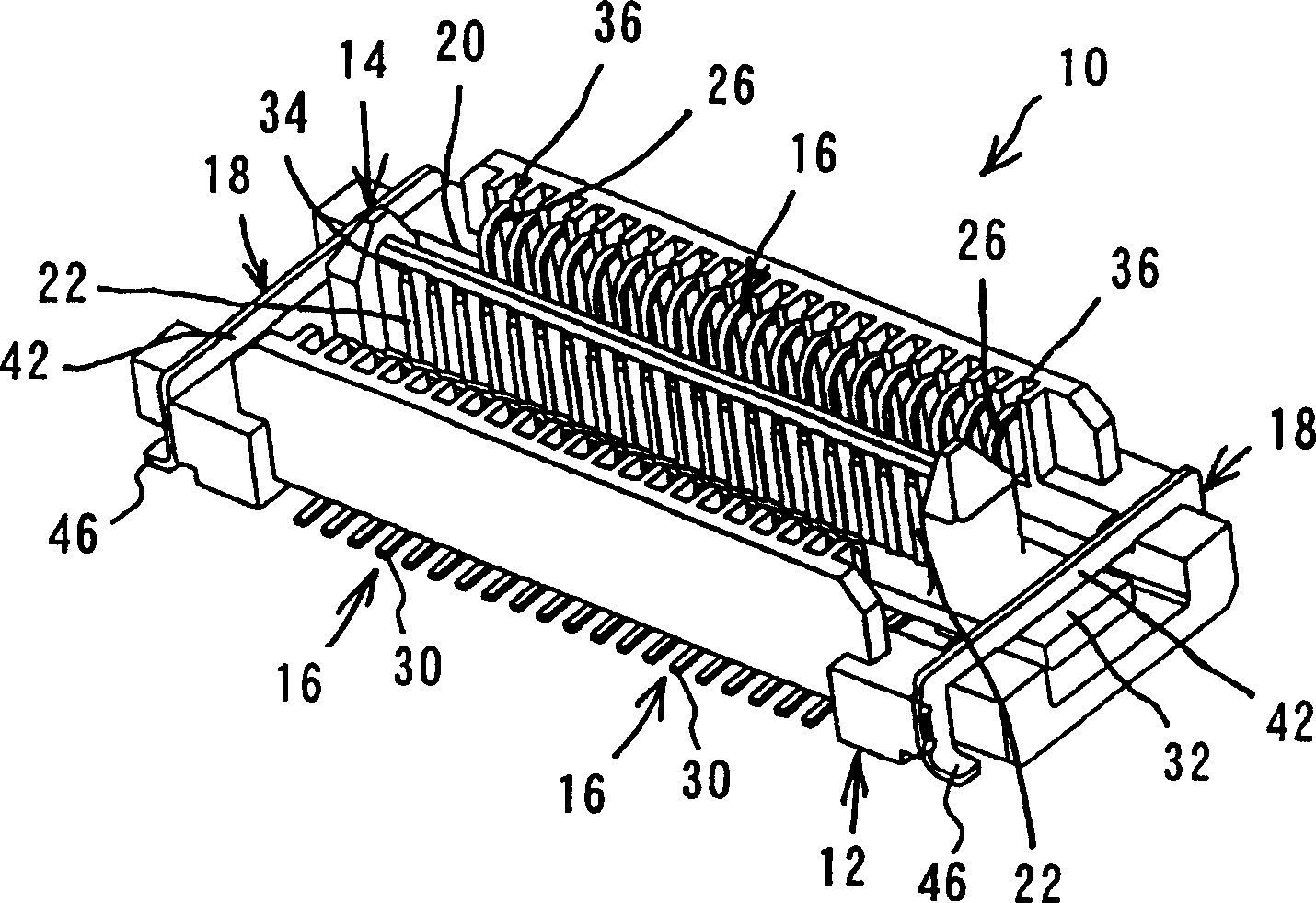
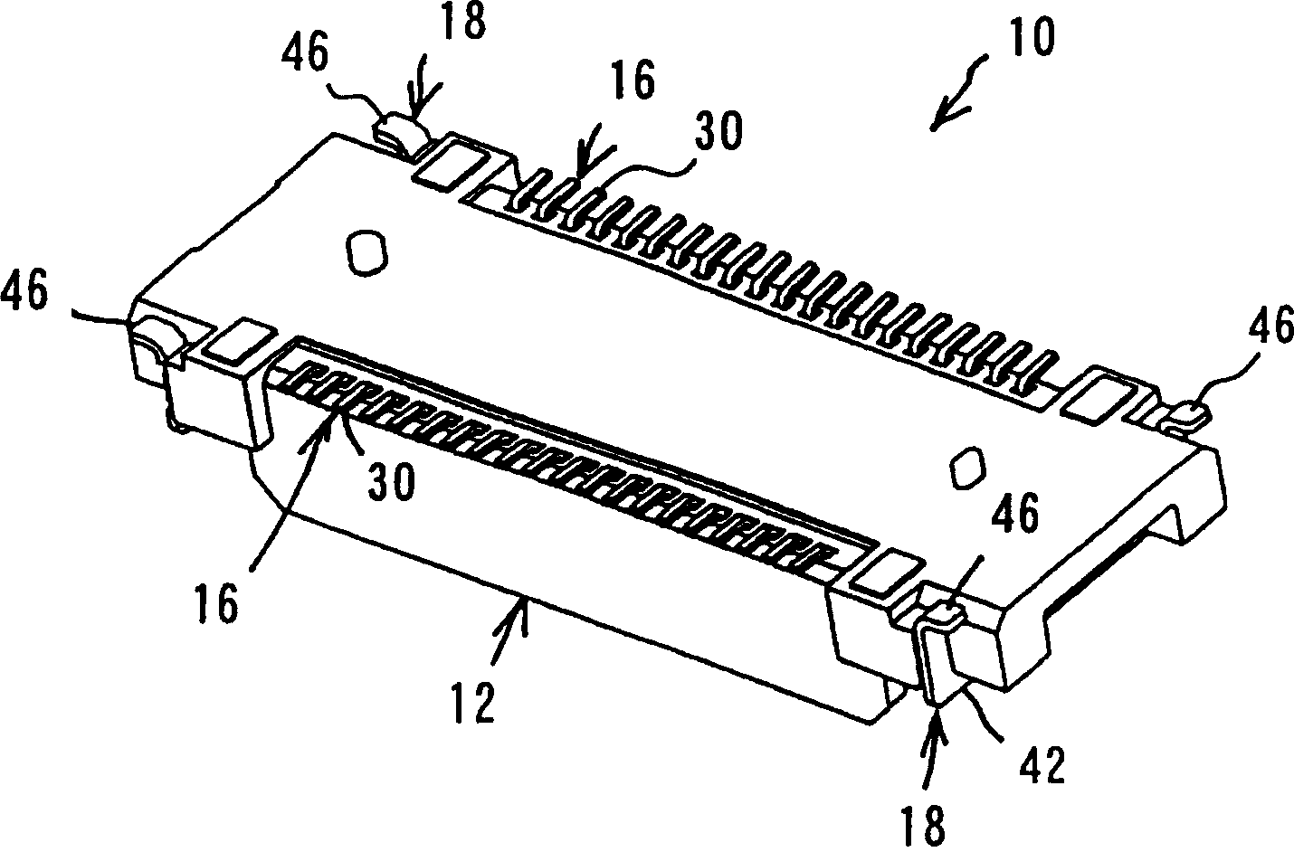
[0037] An embodiment of the connector according to the present invention will be explained with reference to the accompanying drawings 1-5. Figure 1A is a perspective view of the connector according to the present invention seen from the fitting port side. Figure 1B is a perspective view of the connector according to the invention seen from the substrate connection side. Figure 2A is a cross-sectional view of a connector and a mating connector according to the invention. Figure 2B is a cross-section of a connector according to the invention assembled with a mating connector. Figure 3A It is a perspective view of the fixing block seen from the mounting port side. Figure 3B It is a perspective view of the movable case seen from the mounting port side. Figure 4 is a perspective view of the touchpoint. Figure 5 is a perspective view of the fixed wing.

[0038] The connector 10 according to the present invention mainly includes a fixed block 12 , a movable housing 14 , ...


PUM


Abstract

A connector includes contacts and an insulator. Each contact includes a contact portion, a first fixed portion, an elastic portion substantially in the form of a crank, a second fixed portion and a connection portion. The insulator includes a fixation block to which the second fixed portions are fixed, and a movable housing to which the first fixed portions are fixed. The movable housing is fixed only to the contacts and held by the elastic portions in a floating condition away from the bottom surface of the fixation block. The fixation block has a wall for preventing short circuit when the connector is being mounted on a substrate. A floating amount of more than 0.7 mm can be achieved with a simple construction without causing short circuit with a substrate when the connector is being fitted with a mating connector and without causing any failed connection.

Description

technical field [0001] The present invention relates to a connector used in electrical and electronic equipment such as car navigation systems, and more particularly to a connector having a floating structure that allows the connector to be assembled with a mating connector, even in There is a certain positional deviation in between. Background technique [0002] Generally, in order to connect two substrates, two connectors (for example, a plug connector and a receptacle connector) are used. Each of these two connectors essentially comprises a plurality of contacts and an insulator made of electrically insulating material for arranging the clamping contacts. When the two connectors are respectively connected to the substrate by soldering or the like, some positional deviation inevitably occurs between the two connectors. Therefore, in many cases, any connector is a floating structure to accommodate or eliminate this positional deviation. [0003] In the following Patent D...

Claims


Application Information

Patent Timeline
Patent Type & Authority Applications(China)
IPC IPC(8): H01R13/629H01R13/631H01R12/22H01R24/00
CPCH01R12/52H01R13/26H01R12/725
Inventor 古口康之小岛功
Owner DDK LTD
Why Eureka
Try Eureka