
Gear stepping type stepless speed change device

A step-by-step technology for step-by-step transmission, which is applied in the direction of gear transmission, transmission, belt/chain/gear, etc., can solve the problems of difficult and large-displacement automobile applications, short life, large wear, etc., and achieve cost reduction Low, easy to control, wide range of shifting effects

Inactive Publication Date: 2006-12-20
秦桂强
View PDF0 Cites 8 Cited by
  • Summary
  • Abstract
  • Description
  • Claims
  • Application Information

AI Technical Summary

Problems solved by technology

Currently, the continuously variable transmissions used in automobiles are only known to be used in a small amount of steel belt type continuously variable transmissions. Its superior performance is incomparable to the stepped transmissions, but there are also some problems, such as easy slipping, Large wear, short life, difficult to apply to large-displacement vehicles, etc.

Method used


Image

  • Gear stepping type stepless speed change device
  • Gear stepping type stepless speed change device
  • Gear stepping type stepless speed change device

Examples


Embodiment 1

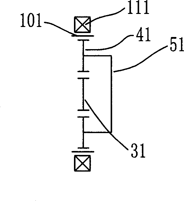
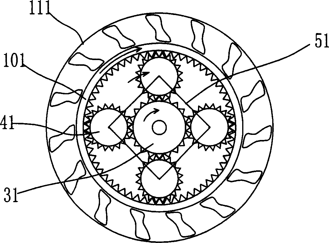
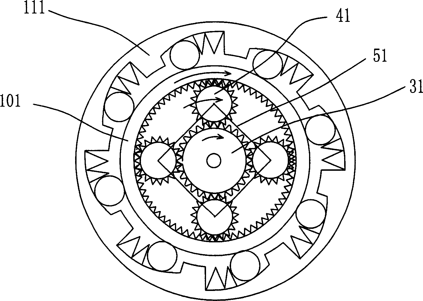
[0014] Embodiment one: as attached Figure 4 As shown, the device mainly includes a support frame 11, and a planetary gear train is installed in the support frame 11. The gear train includes: a driving sun gear 31, the driving sun gear 31 is fixedly connected to the input shaft 21, and there are three to 6 output planetary gears 41, the output planetary gears 41 are installed on the planetary gear frame 51, the planetary gear frame 51 is connected to the output shaft 61, and a speed regulating sun gear 71 is also arranged on the input shaft 21 in front of the driving sun gear 31, and the speed regulating The sun gear 71 is externally engaged with 3 to 6 speed-regulating planetary gears 91, the speed-regulating planetary gears 91 are installed on the planetary gear frame 81, the planetary gear frame 81 is fixed on the input shaft 21, the speed-regulating planetary gears 91, the output planetary gear 41 Engaging with the ring gear 101, there is a one-way bearing, that is, a one-...

Embodiment 2

[0016] Embodiment two; Figure 5 As shown, the continuously variable transmission device mainly includes a support frame 11, and a planetary gear train is installed in the support frame 11. The gear train includes a driving sun gear 31. The driving sun gear 31 is fixedly connected to the input shaft 21 and engages along the periphery of the driving sun gear 31. There are 3 to 6 output planetary gears 41, the output planetary gears 41 are installed on the planetary gear frame 51, the planetary gear frame 51 is connected to the output shaft 61, and a speed regulating sun gear 71 is also arranged on the input shaft 21 in front of the driving sun gear 31 There are 3 to 6 speed-regulating planetary gears 92 externally meshed with the speed-regulating sun gear 71, each speed-regulating planetary gear 92 is installed on the planetary gear frame 51, and the revolution diameter of the speed-regulating planetary gear 92 is greater than the revolution diameter of the planetary gear 41, ea...


PUM


Abstract

The invention relates to a gear stepless speed changer, which comprises: planet gear system and one-way bearing as one-way clutch, wherein the gear system comprises an active sun wheel connected to the power input; there are 3-6 output planet wheels meshed with the circumference of active sun wheel; the output planet wheel is mounted on the planet wheel support fixed with the power output; each output planet wheel is meshed with one tooth ring; one-way bearing is arranged on the tooth ring; the output planet wheel and the planet wheel support are the output; the revolution speed of planet wheel support is the output rotation speed; the active sun wheel is the input; the tooth ring is the input used when changing speed; the power of driving tooth ring can be obtained from the input axle; the rotation direction of tooth ring is same as active sun wheel; the one-way bearing sheathes the tooth ring or the element connected to the tooth ring, to rotate the tooth ring at single direction. The invention has simple structure, stepless speed change, and wider speed range.

Description

technical field [0001] The invention relates to a speed change device, in particular to a gear step-type continuously variable speed change device with simple structure and large speed change range. Background technique [0002] With the further deepening of the industrialization process, transmissions are widely used in various occasions and fields, and the most common ones are used in various vehicles and other mechanical equipment. There are two types of transmissions, step and stepless. In today's automotive field, most of the transmissions are stepped. Because the efficiency of the stepped transmission is not as high as that of the continuously variable transmission, people have been researching and developing a reliable and durable continuously variable transmission to replace the existing stepped transmission in the automobile manufacturing industry. Currently, the continuously variable transmissions used in automobiles are only known to be used in a small amount of ...

Claims


Application Information

Patent Timeline
Patent Type & Authority Applications(China)
IPC IPC(8): F16H3/44
Inventor 秦桂强
Owner 秦桂强
Learn More