
Drum structure of dryer

A technology of dryers and drums, which is applied in household dryers, washing devices, textiles and papermaking, etc. It can solve the problems of difficult installation, easily damaged transmission belts, friction between conveyor belts and welding parts, etc., to improve drying efficiency and prolong service life , the effect of reducing friction

Inactive Publication Date: 2006-12-13
LG ELECTRONICS (TIANJIN) APPLIANCES CO LTD
View PDF0 Cites 1 Cited by
  • Summary
  • Abstract
  • Description
  • Claims
  • Application Information

AI Technical Summary

Problems solved by technology

Therefore, the installation member and the transmission belt that is wound on the outer peripheral surface of the drying cylinder to rotate the drying cylinder will interfere with each other, and the transmission belt will be easily damaged.
[0008] When the surface groove of the drying drum is cut, burrs will be generated. When the installation member is inserted into the installation lifter, the burr will cause difficulties in installation.
[0009] The drying drum is a cylindrical structure formed by welding the two ends of a right-angled quadrilateral plate after rolling it up. The welded part is raised upwards, which is likely to cause friction between the conveyor belt and the welded part.

Method used


Image

  • Drum structure of dryer
  • Drum structure of dryer
  • Drum structure of dryer

Examples


Embodiment Construction

[0035] Embodiments of the present invention will be further described below in conjunction with the accompanying drawings.

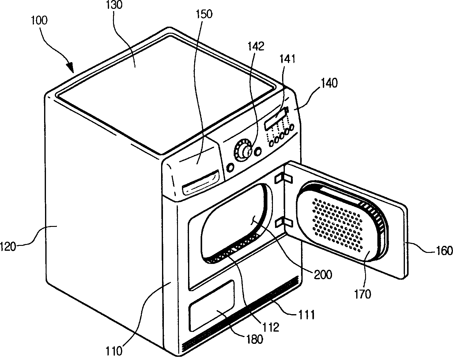
[0036] figure 1 It is a three-dimensional schematic diagram of the external structure of the present invention.

[0037] Such as figure 1 As shown, the dryer 100 provided by the present invention includes: a front cover 110, a side cover 120, and a top cover 130 that constitute the appearance; it is arranged above the front cover 110 and has a setting button 142 and a display screen for inputting the operating conditions of the dryer 100. 141 of the control panel 140 .

[0038] A condensed water box 150 for collecting condensed water generated during the drying process is inserted into a side of the control panel 140 close to the outside, and an opening is provided in the approximate center of the front cover 110 . There are also a door 160 for opening and closing the opening, and a door lint filter 170 pasted on the back of the door 160 to remove clo...


PUM


Abstract

The invention discloses a roller structure of desaturator, comprising: roller body; exaltation piece, the roller body is cylinder model has certain length and width, the two end of plate-like conjoined by plate-like manner; banding disc which forming from one side end of roller body to center direction, there are at least one coining projection set on disc to strengthen the disc strength; roller head parallels to center axis forming by bending a part of disc; roller back wall which set in another side end of roller body. The useful effect of this invention is: the drying-roller of this invention is consisted of roller head, roller body and roller back wall, so the thickness of roller is less than the roller of existing technique. The invention sets coining projection which used to strengthen the strength, can put more matter to be dried in roller, improving drying efficiency. The jointing part of drying-roller surface is hided inner roller, the external surface is very smooth, decreasing the friction between conveyor-bands, prolonging life duration.

Description

technical field [0001] The present invention relates to a dryer, in particular to a drum structure arranged inside the dryer. Background technique [0002] Generally, the dryer is a machine that uses the heat generated by an electric or gas heating device to dry the clothes in the drum after putting the clothes into the drum of the clothes dryer. Recently, the demand for dryers has been increasing. [0003] The clothes dryer in the prior art includes: a drying drum for storing objects to be dried; a heater and a blower fan for supplying hot air to the inside of the drum; and a condenser for exchanging heat between the circulating air inside the drum and the outside air. [0004] A lifting member for lifting the object to be dried is arranged inside the drying drum. [0005] An opening for inputting the object to be dried is provided on the front of the drying drum, and the peripheral surface of the opening is provided on the front cover of the dryer. There are radial bear...

Claims


Application Information

Patent Timeline
Patent Type & Authority Applications(China)
IPC IPC(8): D06F58/04
Inventor 金昌旭
Owner LG ELECTRONICS (TIANJIN) APPLIANCES CO LTD
Learn More