Eureka AIR delivers breakthrough ideas for toughest innovation challenges, trusted by R&D personnel around the world.

Method for implementing whole optical virtual private network in passive optical network

A passive optical network and virtual private network technology, applied in the field of all-optical virtual private network, can solve the problems of increasing system cost, unable to support simultaneous transmission of virtual private network internal services and transmission of non-virtual private network services, etc., to achieve The effect of reducing hardware costs

Inactive Publication Date: 2006-12-06
SHANGHAI JIAO TONG UNIV
View PDF0 Cites 12 Cited by
  • Summary
  • Abstract
  • Description
  • Claims
  • Application Information

AI Technical Summary

Problems solved by technology

The disadvantage of this technology is that each optical network unit requires two transmitters and two receivers, which greatly increases the cost of the system
It is also found in the search that among the prior art supporting communication within the optical network unit group, the article "A Packet-Switched Waveband-selective PON Enabling Optical Internetworking among ONUs" published in European Conference on Optical Communication 2005 (2005 European Optical Communication Conference) Band Selective Passive Optical Network for Realizing Optical Interconnection and Packet Switching between Optical Network Units)" discloses a technology, that is, a fast adjustable reflector is placed at the end of the optical line to reflect the data packets, but this solution cannot support the simultaneous sending of VPN internal services and the transmission of non-VPN services

Method used


Image

  • Method for implementing whole optical virtual private network in passive optical network
  • Method for implementing whole optical virtual private network in passive optical network
  • Method for implementing whole optical virtual private network in passive optical network

Examples


Embodiment Construction

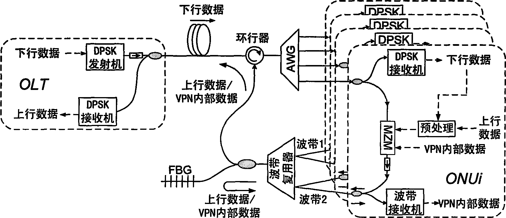
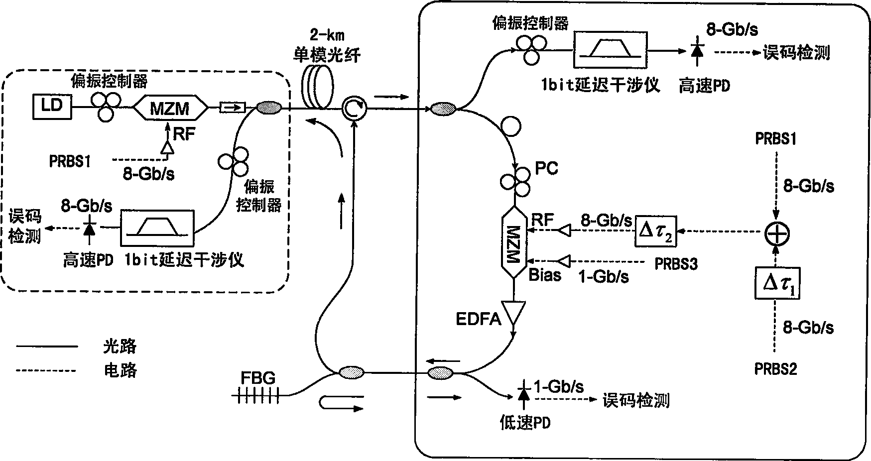
[0024] like figure 1 As shown, the optical line terminal sends downlink data to different optical network unit ends by changing the emission wavelength of the tunable wavelength transmitter, and the modulation format is differential phase shift keying (DPSK). After the downlink data is decomposed and multiplexed by the circulator and the arrayed waveguide grating, it reaches the corresponding optical network unit. In the optical network unit, the downlink optical signal is divided into two parts by the optical splitter, and part of the downlink data is obtained by the differential phase shift keying receiver. The preprocessed uplink data and the internal data of the virtual private network drive the Mach-Zehnder modulator (MZM) to perform differential phase shift keying erasure and rewrite on the other part, and perform differential phase shift keying / intensity modulation quadrature modulation, The obtained phase information and amplitude information of the uplink optical sig...


PUM


Abstract

The method for realizing full optical virtual private network (VPN) in passive light network includes steps: optical line terminal (OLT) transmits down going optical signal in format of differential phase shift keying (DPSK) modulation, and down going electric signal is obtained after conversion; pretreatment for upgoing electric signal is completed inside optical network unit; not modulated down going optical signal is injected to Mach Zehnder modulator to carry out modulation, and DPSK modulation is carried out for pretreated upgoing electric signal; internal signal of VPN is input to bias port of the modulator, which drives fluctuation of the signal in small range to generate format of DPSK / intensity modulation; through band multiplexer, optical signal and upgoing optical signal from optical network unit are multiplexed; optical network unit receives internal data of VPN in optical signal fed back, and OLT receives data corresponding to internal service in non VPN.

Description

technical field [0001] The invention relates to a method in the technical field of optical fiber communication, specifically, a method for realizing an all-optical virtual private network in a passive optical network. Background technique [0002] Utilizing the existing low-cost optical devices, the passive optical network (PON) has become an attractive solution for users to realize broadband access because of its simple structure and low cost. Traditionally, it adopts a tree topology, where the optical line terminal (OLT) or central office delivers services to remote nodes (RN) through a long optical fiber, where the optical power is split and further transmitted to many optical network units (ONUs). ). Each optical network unit can provide services for multiple users. In order to further improve the flexibility and reliability of the network, it is necessary to support the internal communication of the optical network unit and establish an all-optical virtual private net...

Claims


Application Information

Patent Timeline
IPC IPC(8): H04B10/12H04L12/42H04B10/25H04B10/556
Inventor 田玥苏翼凯
Owner SHANGHAI JIAO TONG UNIV
Why Eureka
Eureka Blog
Learn More