
Traverse device for yarn, and textile machinery including the same

A technology of traversing device and yarn, which is used in transportation and packaging, electromechanical devices, electric components, etc., can solve the problems that the structure of document 2 cannot be considered reasonable, lengthened, and inertia increased.

Inactive Publication Date: 2006-12-06
MURATA MASCH LTD
View PDF0 Cites 8 Cited by
  • Summary
  • Abstract
  • Description
  • Claims
  • Application Information

AI Technical Summary

Problems solved by technology

Therefore, considering this point of view, the structure of Document 2 cannot be considered reasonable
[0010] On the other hand, considering that a large torque can be obtained by generating electromagnetic force in the same direction against the paired left and right coil sides, the structure of document 3 is superior to that of documents 1 and 2, however, the pair of left and right coil sides is in any pivotal position The positions must always be in the corresponding separated left and right spaces, so, as a result, the coil side connecting the left and right coil sides (the coil side that does not contribute to torque) must be lengthened, resulting in increased inertia
[0011] The coil side connecting the left and right is long as described above, and therefore also increases the space required for pivoting, so there is still room for improvement in the compactness of the yarn guide drive section

Method used


Image

  • Traverse device for yarn, and textile machinery including the same
  • Traverse device for yarn, and textile machinery including the same
  • Traverse device for yarn, and textile machinery including the same

Examples


Embodiment Construction

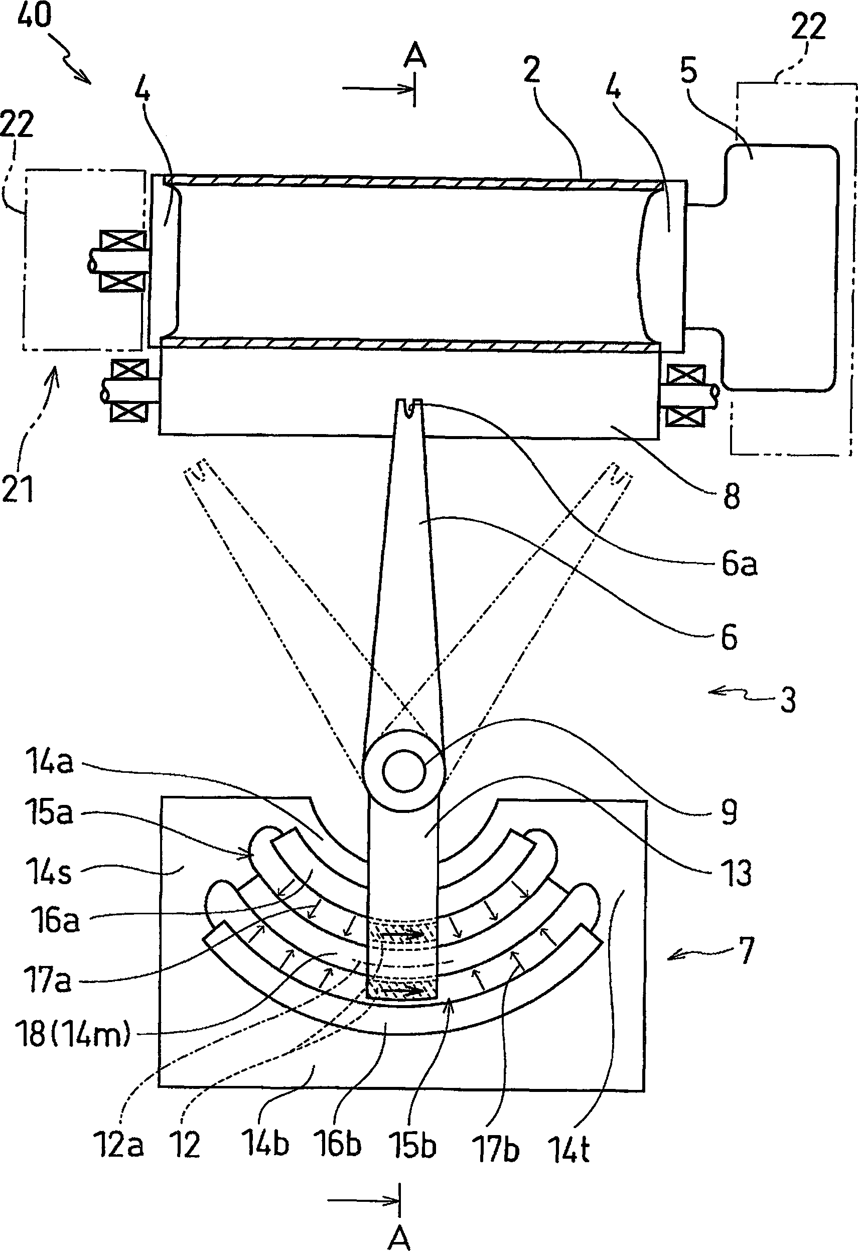
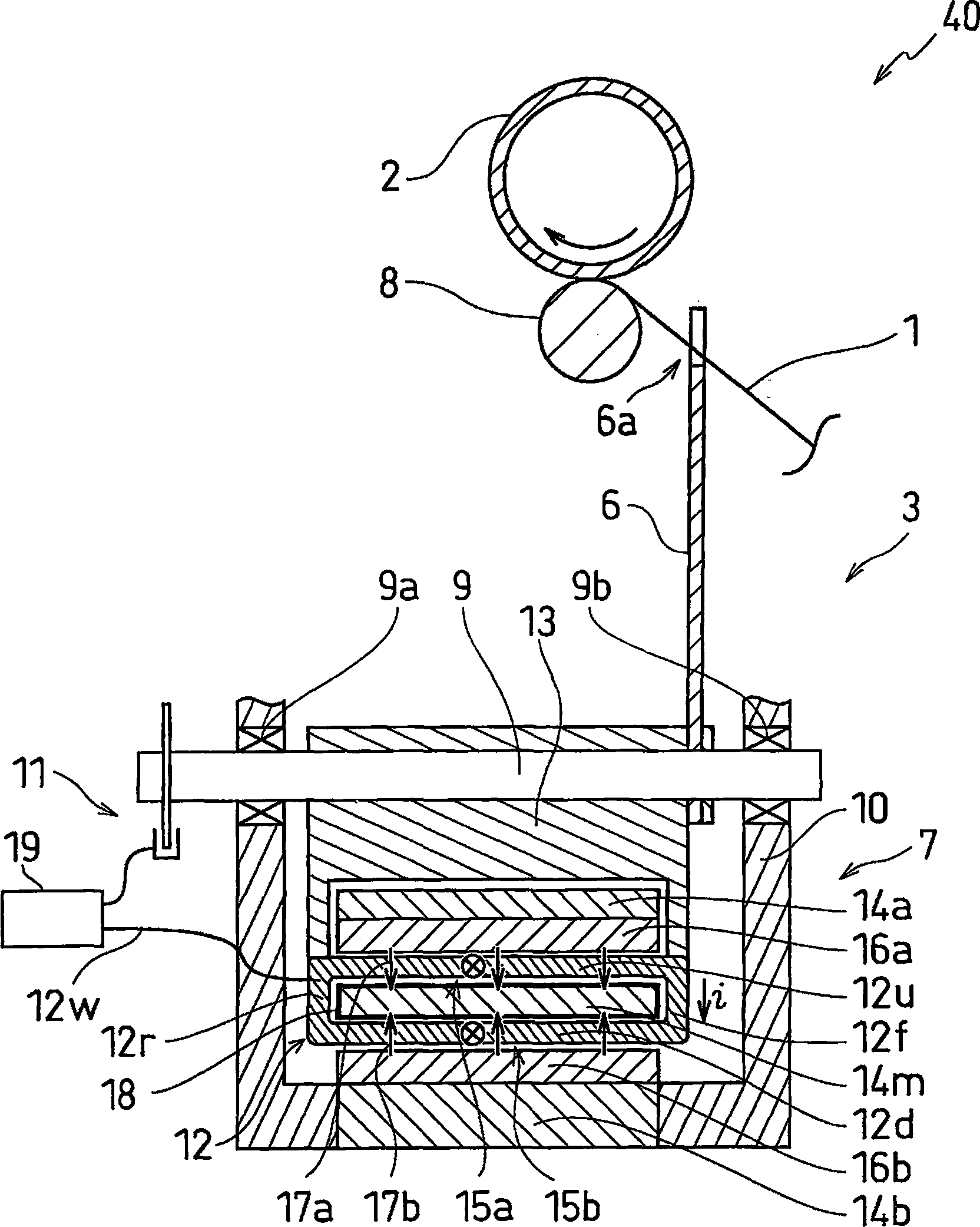
[0044] Next, a first embodiment of the traversing device according to the present invention will be described with reference to the drawings.

[0045] Here, an example of an automatic winder using the present invention is explained as an example of a fiber machine.

[0046] figure 1 is a schematic front view of the winding section of the automatic winding machine according to the first embodiment.

[0047] figure 2 is along figure 1 The cross-sectional view of the middle arrow A-A.

[0048] Figure 5 is a schematic front view of the winding unit of the automatic winding machine according to the embodiment of the present invention.

[0049] First, refer to Figure 5 The yarn winding unit 102 of the automatic winding machine 101 will be described.

[0050] Figure 5 The yarn winding unit 102 of the illustrated automatic winding machine 101 winds the yarn 1 unwound and supplied from the yarn supply bobbin 103 around the winding bobbin 2 while the yarn is traversed by the t...


PUM


Abstract

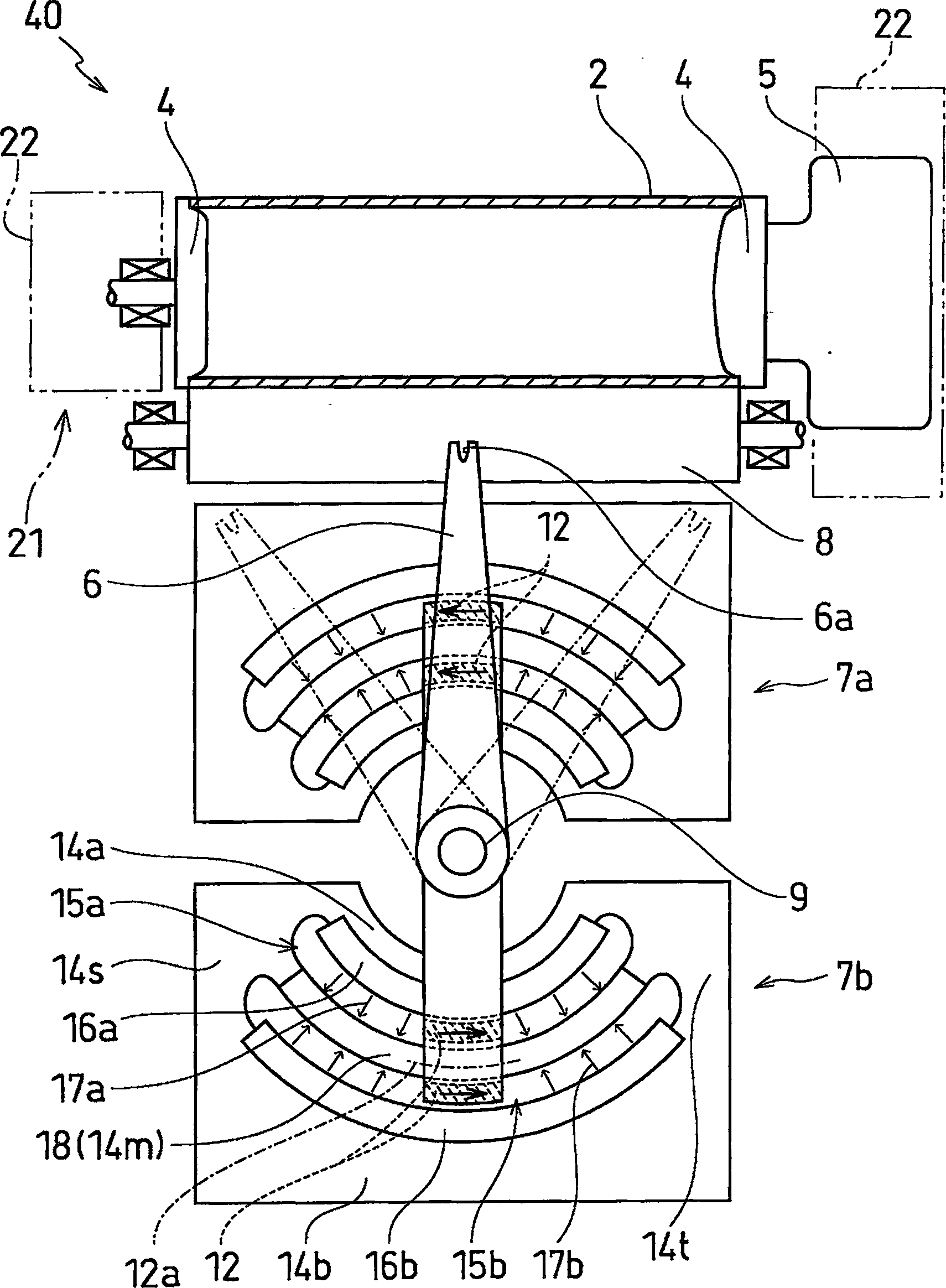
A traverse device (3) has an arm driving part (7) which rotatively reciprocates an arm (6) having a yarn guide (6a) to traverse a yarn (1) on a takeup bobbin (2) that winds the yarn (1). The arm driving part (7) comprises an electrical coil (12) provided in the arm (6), two yokes (14a, 14b) formed into arc shapes around the center of axis of an arm shaft (9) as the center of rotative movement of the arm (6), and an air gap (15) that is sandwiched between the two yokes (14a, 14b) and has magnetic fields formed inside, and a part of the electrical coil (12) is inserted in the air gap (15). The respective two yokes (14a, 14b) are provided with permanent magnets (16a, 16b), a central yoke (14m) that divides the air gap (15) into two rows is provided, and in the respective two-row air gaps (15a, 15b), magnetic lines (17a, 17b) turned in the radial direction and being opposite each other are formed by the permanent magnets (16a, 16b). A part of the electrical coil (12) is inserted in the respective two-row air gaps (15a, 15b) so as to surround the central yoke (14m).

Description

technical field [0001] The present invention relates to a yarn traversing device for traversing a yarn to be wound by a winding bobbin. Furthermore, the invention relates to a fiber machine comprising such a traversing device. Background technique [0002] Regarding this type of traversing device, Japanese Published Unexamined Patent Application No. 2001-72334 (Document 1) discloses a structure in which a yarn guide for guiding a yarn is attached to the end side of an arm, and the other end of the arm is The side or middle portion is connected to a shaft about which the arm can swing as a pivot, and a voice coil motor is connected to the other end side of the arm. In this document 1, a voice coil motor includes a stator including a sector-shaped permanent magnet extending around an axis, and a movable element including a sector-shaped air-core coil disposed around the stator. [0003] In addition, Japanese Published Unexamined Patent Application No. 05-304755 (Document 2) ...

Claims


Application Information

Patent Timeline
Patent Type & Authority Applications(China)
IPC IPC(8): B65H54/06B65H54/28
CPCB65H2701/31B65H54/2827H02K33/18B65H54/2833H02K41/03
Inventor 木野义浩正井哲司
Owner MURATA MASCH LTD
Learn More