
Substrate conveying device

A technology for conveying substrates and substrates, applied to conveyors, conveyor objects, transportation and packaging, etc., can solve problems such as inability to transfer substrates, speed differences, etc., and achieve the effect of reducing friction

Inactive Publication Date: 2006-11-22
DAINIPPON SCREEN MTG CO LTD
View PDF2 Cites 18 Cited by
  • Summary
  • Abstract
  • Description
  • Claims
  • Application Information

AI Technical Summary

Problems solved by technology

Therefore, a speed difference occurs during substrate conveyance between the backup roller 6 side and the holding roller 7 side of the substrate conveyance path, and the substrate cannot be conveyed straight on the substrate conveyance path.

Method used


Image

  • Substrate conveying device
  • Substrate conveying device
  • Substrate conveying device

Examples


Embodiment Construction

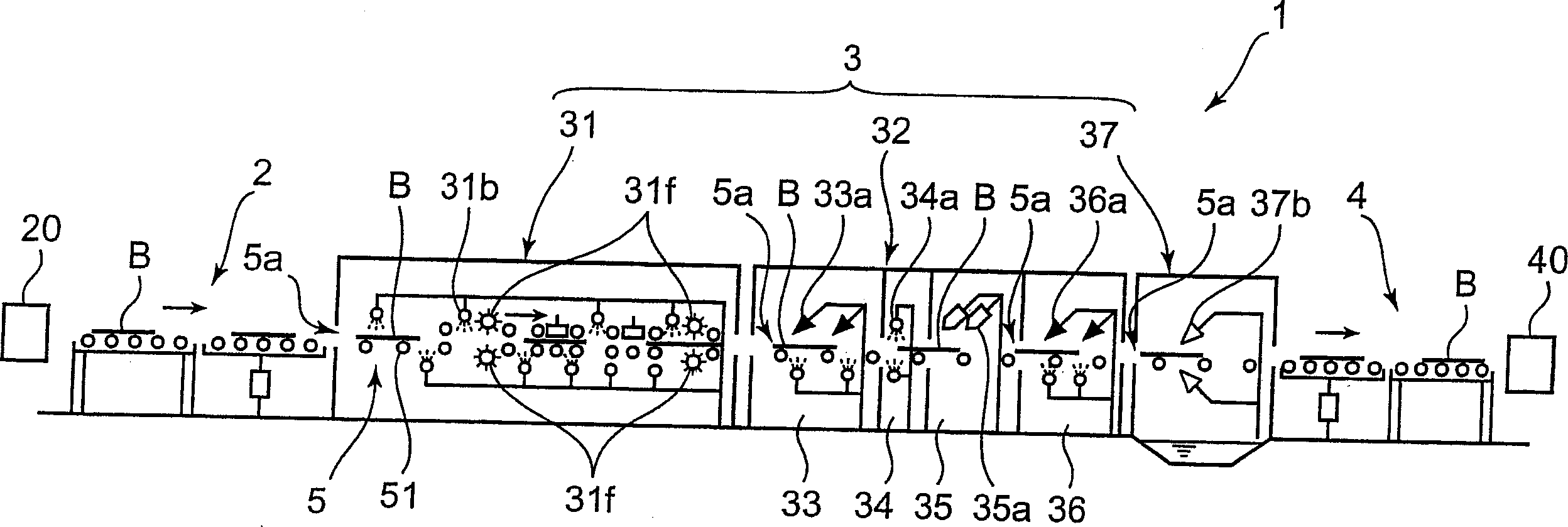
[0037] Next, a substrate transfer device according to an embodiment of the present invention will be described with reference to the drawings. figure 1 It is an explanatory view showing a substrate processing apparatus including a substrate transfer apparatus according to an embodiment of the present invention. As shown in the figure, the substrate processing apparatus 1 is arranged in series: a substrate introduction part 2 that receives a substrate B from a previous process, a processing apparatus main body 3 having a processing space for the substrate B inside, and a substrate for delivering the processed substrate B to the substrate. Substrate lead-out unit 4 in the post-process. The substrate processing apparatus 1 transports a substrate in the order of a substrate introduction unit 2 , a processing apparatus main body 3 , and a substrate output unit 4 , and performs predetermined processing on a substrate B. The substrate introduction part 2 or the substrate export par...


PUM


Abstract

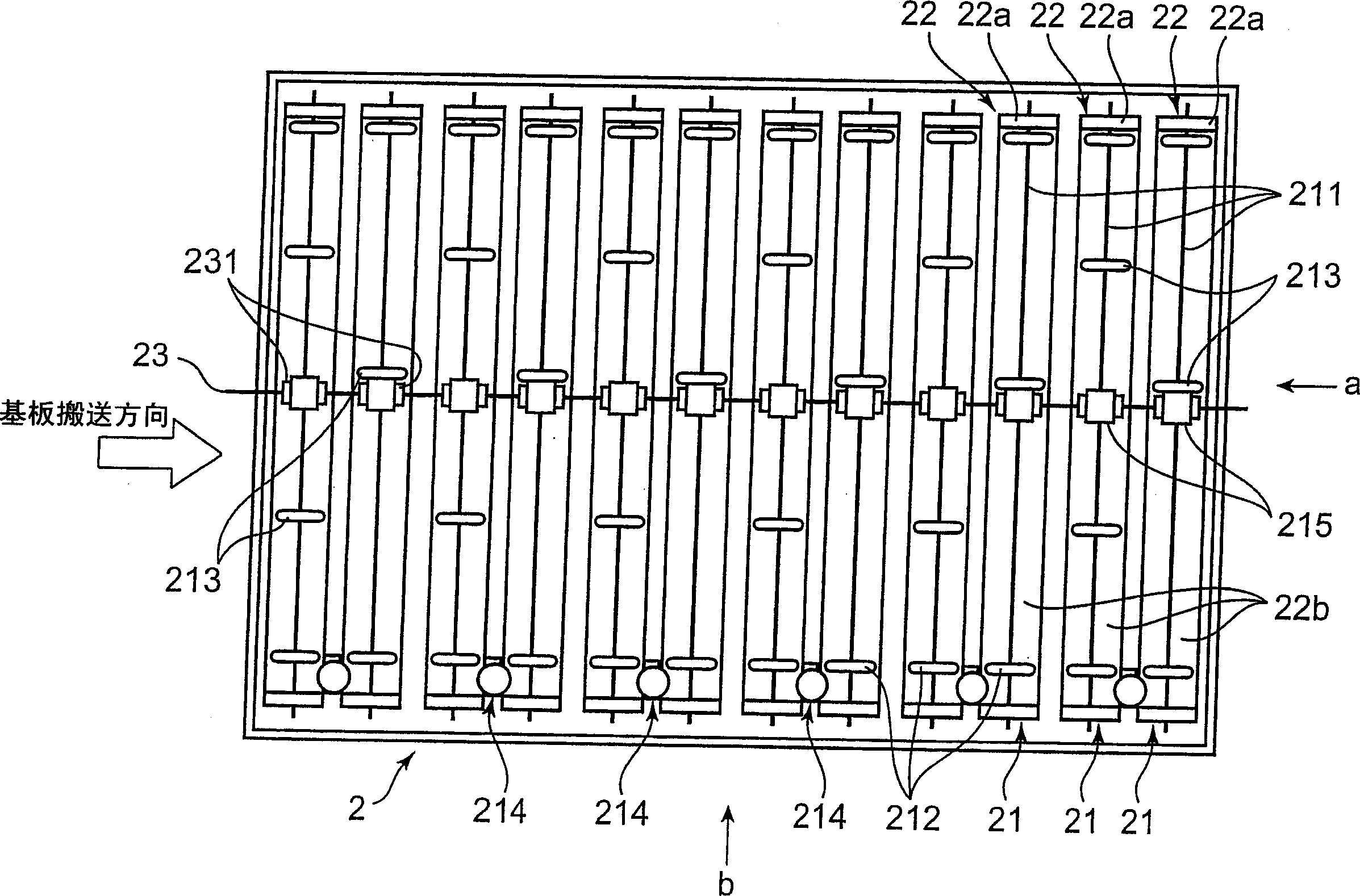
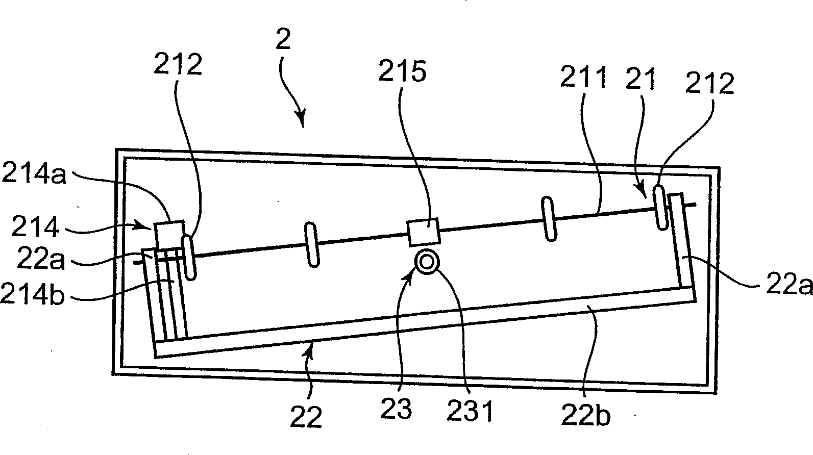
To provide a substrate carrying device, capable of changing a substrate to an inclined attitude when the substrate is being carried straight on a substrate carrying passage without reducing throughput of a substrate processing. Each magnet gear 231 of a drive shaft 23 and a magnet gear 215 of each carrying roller 21 are disposed close to each other but not in contact. As the drive shaft 23 rotates by rotation drive force from a drive motor or the like, rotation drive force is transmitted from the magnet gear 231 of the drive shaft 23 toward a magnet gear 215 of the carrying roller 21. The carrying rollers 21 are gradually largely inclined from a horizontal attitude in a perpendicular direction to the carrying direction of the substrate B as they go from the carrying roller 21 upstream of the substrate carrying direction to the carrying roller 21 on the downstream side.

Description

technical field [0001] The present invention relates to a substrate conveyance device that conveys a substrate by a plurality of conveyance rollers arranged in parallel. Background technique [0002] Conventionally, there is known a substrate transfer apparatus that transfers a substrate in an inclined posture relative to a substrate processing unit so that a processing liquid supplied to the substrate surface during substrate processing can be dispersed well from the substrate surface. As a substrate processing apparatus using such a substrate transfer apparatus, there is, for example, a substrate processing apparatus in which, as shown in Patent Document 1 below, when a substrate in a horizontal posture is received, the direction perpendicular to the substrate transfer direction of the substrate transfer path One end moves upward to change the substrate to an inclined posture, and on the downstream side of the substrate processing section, one end in the direction perpendi...

Claims


Application Information

Patent Timeline
Patent Type & Authority Applications(China)
IPC IPC(8): B65G13/00B65G13/11B65G47/22B65G47/52
CPCB65G13/11B65G17/48B65G23/08B65G47/22B65G49/067
Inventor 松本隆雄山本悟史
Owner DAINIPPON SCREEN MTG CO LTD
Learn More